Playground · research instrument

DSP · Audio

Acoustic Beamforming — Delay & Sum

Set the microphone spacing, the element count, the steer angle and the frequency. The polar pattern, the half-power beamwidth, the directivity index and the spatial-aliasing ceiling are solved exactly, from the same module the page's unit tests drive.

Independent research instrument — not claimed as MakerPortal shipped product code. Methods, equations, assumptions, and limitations are disclosed so you can inspect what the page does and does not establish.

Beamformer controls and directivity pattern

Array geometry

Speed of sound fixed at 343 m/s (dry air, 20 °C). It scales every frequency on this page linearly — at 0 °C the aliasing ceiling falls about 3%.

Directivity pattern · full plane

|B(θ)| in dB, 0 dB at the outer ring

No grating lobe

2 elements at 50 mm, steered 0°, at 3430 Hz.

Solved for this geometry

Directivity index
3.01 dB
−3 dB beamwidth
60.0°
Aliasing ceiling c/2d
3430 Hz
Grating onset, this steer
6860 Hz
Spacing d/λ
0.500
Aperture (N−1)d
50.0 mm
Peak sidelobe
none
Max TDOA across array
145.8 µs

The number that decides the design

Directivity index across the audio band

50 Hz → 16 kHz, log scale

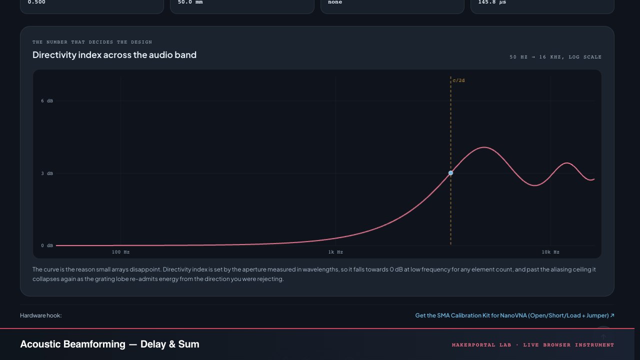
The curve is the reason small arrays disappoint. Directivity index is set by the aperture measured in wavelengths, so it falls towards 0 dB at low frequency for any element count, and past the aliasing ceiling it collapses again as the grating lobe re-admits energy from the direction you were rejecting.

What the calculator solves

N omnidirectional elements on the x axis at xn=(n−N−12)dx_n=(n-\tfrac{N-1}{2})d, a far-field plane wave from angle θ\theta measured from broadside. The only thing an element at xnx_n sees of θ\theta is the direction cosine sin⁡θ\sin\theta, and every consequence below follows from that one fact.

01 · The beam

B(θ)=1N∑n=0N−1e jkxn(sin⁡θ−sin⁡θs),k=2πfcB(\theta)=\frac{1}{N}\sum_{n=0}^{N-1} e^{\,j k x_n(\sin\theta-\sin\theta_s)},\quad k=\frac{2\pi f}{c}

The page evaluates this sum literally, one phasor per microphone. Its closed form is the periodic sinc ∣B∣=∣sin⁡(Nψ/2)Nsin⁡(ψ/2)∣|B|=\left|\frac{\sin(N\psi/2)}{N\sin(\psi/2)}\right| with ψ=kd(sin⁡θ−sin⁡θs)\psi=kd(\sin\theta-\sin\theta_s); the unit test asserts the two agree to 10−1210^{-12} across 6,000 geometries, so the implementation is pinned to an expression written independently of it.

02 · Directivity index

D=∣wHa(θs)∣2wHΓw,Γmn=sinc⁡ ⁣(k∣xm−xn∣)D=\frac{|\mathbf{w}^H\mathbf{a}(\theta_s)|^2}{\mathbf{w}^H\boldsymbol{\Gamma}\mathbf{w}},\quad \Gamma_{mn}=\operatorname{sinc}\!\left(k|x_m-x_n|\right)

Array gain against a spherically isotropic noise field — the honest stand-in for a diffuse room. With uniform weights the numerator is 1 and the denominator is a real double sum. At d=λ/2d=\lambda/2 broadside the coherence matrix is the identity and DI=10log⁡10NDI=10\log_{10}N exactly, which is the anchor the defaults sit on.

03 · Half-power beamwidth

θ−3 dB: ∣B(θ)∣=12(bracketed, then bisected)\theta_{-3\,\mathrm{dB}}:\ |B(\theta)|=\tfrac{1}{\sqrt{2}} \qquad \text{(bracketed, then bisected)}

Found on the pattern, not quoted from 0.886λ/(Nd)0.886\lambda/(Nd). That approximation is asymptotic in N and ignores the 1/cos⁡θs1/\cos\theta_s broadening when the beam is steered — at 40° off broadside the real lobe is 30% fatter than the formula says. When no −3 dB edge exists inside ±90∘\pm 90^\circ the readout says so instead of extrapolating.

04 · Spatial aliasing

dλ(1+∣sin⁡θs∣)≥1  ⟹  fgrating=cd (1+∣sin⁡θs∣)\frac{d}{\lambda}\left(1+|\sin\theta_s|\right)\ge 1 \;\Longrightarrow\; f_{\mathrm{grating}}=\frac{c}{d\,(1+|\sin\theta_s|)}

A grating lobe is a second direction with the same full array gain — the spatial twin of aliasing in a sampled signal. The worst case over every steer angle is endfire, which gives the familiar f=c/(2d)f=c/(2d) ceiling. Steer only broadside and you are allowed an octave more spacing; the calculator prints both so that octave is a decision rather than an accident.

Model boundary. Ideal omnidirectional elements, exact positions, free field, far field, uniform shading, one frequency at a time. Not modelled: element self-noise, sensitivity and phase mismatch between capsules, finite-baffle scattering, near-field wavefront curvature, fractional-delay interpolation error, room reflections, and every adaptive weighting (MVDR, superdirective, GSC). Each of those moves a real measurement the same way — less rejection than these curves promise, never more. The deep nulls go first.

The same geometry, run backwards: direction of arrival

A beamformer applies a delay it already knows. A direction finder measures the delay it does not: τ=Lsin⁡θ/c\tau = L\sin\theta/c across an aperture L=(N−1)dL=(N-1)d, then inverts to θ=arcsin⁡(cτ/L)\theta=\arcsin(c\tau/L). The readouts above give you the whole budget — the widest arrival-time difference the aperture can produce is printed as max TDOA, and on a 50 mm two-microphone baseline it is 145.8 µs.

That number is what makes sample-rate arithmetic concrete. One sample period at 48 kHz is 20.833 µs, which is 14% of the whole usable range. Differentiating θ=arcsin⁡(cτ/L)\theta=\arcsin(c\tau/L) gives dθ/dτ=c/(Lcos⁡θ)d\theta/d\tau = c/(L\cos\theta), so a single sample of timing error is worth 8.2° at broadside, 16.4° at 60°, and 47.2° at 80° on that baseline. The angular cost of pointing near the array axis is not a subtlety; it is the dominant error term.

Sub-sample interpolation — GCC-PHAT with a parabolic peak fit is the usual choice — buys back most of that, and it is the reason a practical two-microphone direction finder works at all. It does not touch the 1/cos⁡θ1/\cos\theta term, and it cannot touch the front-back ambiguity.

Named failure mode · front-back ambiguity

sin⁡(180∘−θ)=sin⁡θ\sin(180^\circ-\theta)=\sin\theta, so a talker at 30° and a talker at 150° produce identical delays at every element. The polar plot draws both lobes for exactly this reason. More microphones on the same line narrow both and remove neither. This is the single most common surprise when a line array meets a real room.

Named failure mode · the near field

Every curve here assumes plane waves. A source closer than a few aperture lengths presents a curved wavefront, the delays stop being linear in xnx_n, and the steering vector is wrong in a way that broadens the main lobe and fills the nulls. On a 50 mm baseline that boundary is a few hundred millimetres — close enough to matter for a handheld device, far enough not to for a room.

Measured, not modelled

For what a seven-capsule 44 mm ring array actually delivers on real speech — SRP-PHAT direction tracking, a superdirective beam, and the octave-band rejection numbers off the recordings — read the UMA-8 field note. This page is the prediction; that one is the instrument.

Gear that turns this into a measurement

Array + capture stack · 38 picks

More gear across every build: the full Gear list →

The beamformer, in forty lines

This is what runs in your browser above, with the argument validation stripped out. No FFT, no library, no adaptation — a delay-and-sum beamformer really is one loop over microphone positions.

Delay-and-sum + directivity index

const C = 343;                      // m/s, dry air at 20 degrees C

// Element positions, centred on the origin.
function positions(n, d) {
  return Array.from({ length: n }, (_, i) => (i - (n - 1) / 2) * d);
}

// Normalised delay-and-sum response at arrival angle theta (radians from
// broadside), steered to theta_s. This IS the beamformer: one phasor per
// microphone, steering delay applied, summed, divided by N.
function response(n, d, thetaS, freq, theta) {
  const k = (2 * Math.PI * freq) / C;
  const u = Math.sin(theta) - Math.sin(thetaS);
  let re = 0, im = 0;
  for (const x of positions(n, d)) {
    re += Math.cos(k * x * u);
    im += Math.sin(k * x * u);
  }
  return Math.hypot(re, im) / n;
}

// Directivity against a spherically isotropic noise field.
// Gamma_mn = sinc(k * |x_m - x_n|); uniform weights make the numerator 1.
function directivityIndexDb(n, d, thetaS, freq) {
  const k = (2 * Math.PI * freq) / C;
  const x = positions(n, d);
  let s = 0;
  for (const xm of x) for (const xn of x) {
    const delta = xm - xn;
    const sinc = Math.abs(k * delta) < 1e-9 ? 1 : Math.sin(k * delta) / (k * delta);
    s += sinc * Math.cos(k * delta * Math.sin(thetaS));
  }
  return 10 * Math.log10((n * n) / s);
}

// The only spacing rule that holds for every steer angle.
const aliasFreeCeilingHz = (d) => C / (2 * d);

Beamforming questions

What is delay-and-sum beamforming?

It is the simplest spatial filter there is. A plane wave arriving off-axis hits the microphones at different times; delay each channel by exactly the amount that cancels that difference for one chosen direction, sum the channels, and signals from that direction add coherently while everything else partially cancels. No adaptation, no statistics, no training — the only inputs are the microphone positions, the speed of sound and the angle you want to listen to. Every result on this page is that operation evaluated exactly, one frequency at a time.
How much noise rejection does a two-microphone array actually give?

Far less than most people expect, and the amount is computable rather than debatable. With uniform delay-and-sum weights the directivity index of a two-element array is 0.00 dB at 125 Hz on a 50 mm baseline, 0.30 dB at 1 kHz, 1.17 dB at 2 kHz and reaches exactly 3.01 dB only at the frequency where the spacing equals half a wavelength — 3430 Hz for 50 mm. Directivity index is set by the aperture measured in wavelengths, so a small array is close to omnidirectional through the whole low end no matter how the processing is described.

What is the spatial-aliasing frequency, and why is it c/(2d)?

Above a certain frequency the array develops a grating lobe: a second direction with full array gain, indistinguishable from the one you steered at. A grating lobe enters the visible region when (d/λ)·(1 + |sin θs|) reaches 1. The worst case over all steer angles is endfire, |sin θs| = 1, which gives d = λ/2 and therefore f = c/(2d) — 3430 Hz for a 50 mm spacing. If you only ever steer broadside the onset is an octave higher at c/d, which is why the calculator reports both numbers instead of collapsing them into one rule of thumb.

Why does the polar plot show two beams when I steer off broadside?

Because a straight line of microphones physically cannot tell front from back. The response depends only on the direction cosine sin θ, and sin(180° − θ) = sin θ, so every arrival angle has a mirror twin on the other side of the array axis. Adding elements narrows both lobes equally and never removes the ambiguity. Breaking it requires geometry that is not a straight line — a second row, a baffle between the capsules, or a directional element.

Why does the beamwidth readout sometimes say the main lobe is unbounded?

Because it genuinely is. When the array is small compared with the wavelength, the response never falls 3 dB below the look direction anywhere in the visible half-space, so there is no half-power edge to report. The calculator returns no number in that case rather than extrapolating one, and the same applies at endfire, where the main lobe is cut off by the ±90° horizon on one side. A beamwidth wider than the space the array can see is not a beamwidth.

Will a real microphone array match these curves?

It will match the main-lobe shape closely and the nulls poorly. This model assumes ideal omnidirectional elements at exactly the stated positions in free space. A real build adds microphone-to-microphone sensitivity and phase mismatch, which fills the deep nulls first; a finite baffle, which scatters sound around the capsules; near-field wavefront curvature for sources within a few aperture lengths; and room reflections, which arrive from directions the beamformer is rejecting and dominate past the critical distance. All four move a measurement in the same direction: less rejection than the theory promises, never more.

Shareable still

The instrument, captured—not illustrated.

This 16:9 frame is rendered from the real browser instrument above. It is the page's canonical preview for image search, link unfurls, and posts that need to show what the tool actually does.

Download 1280 × 720 JPEG
Acoustic Beamforming Calculator — live MakerPortal instrument screenshot
Canonical capture · real UI · no generated scientific artwork