Hardware build / Mic arrays
Acoustic Beamforming on iPhone: UMA-8
Use a miniDSP UMA-8 mic array with an iPhone for direction finding and a steerable beam: 1.2 dB broadband, but at least 15 dB at 4 kHz per octave band.

Joshua HriskoPrincipal Engineer
14 min readSan Francisco, CA
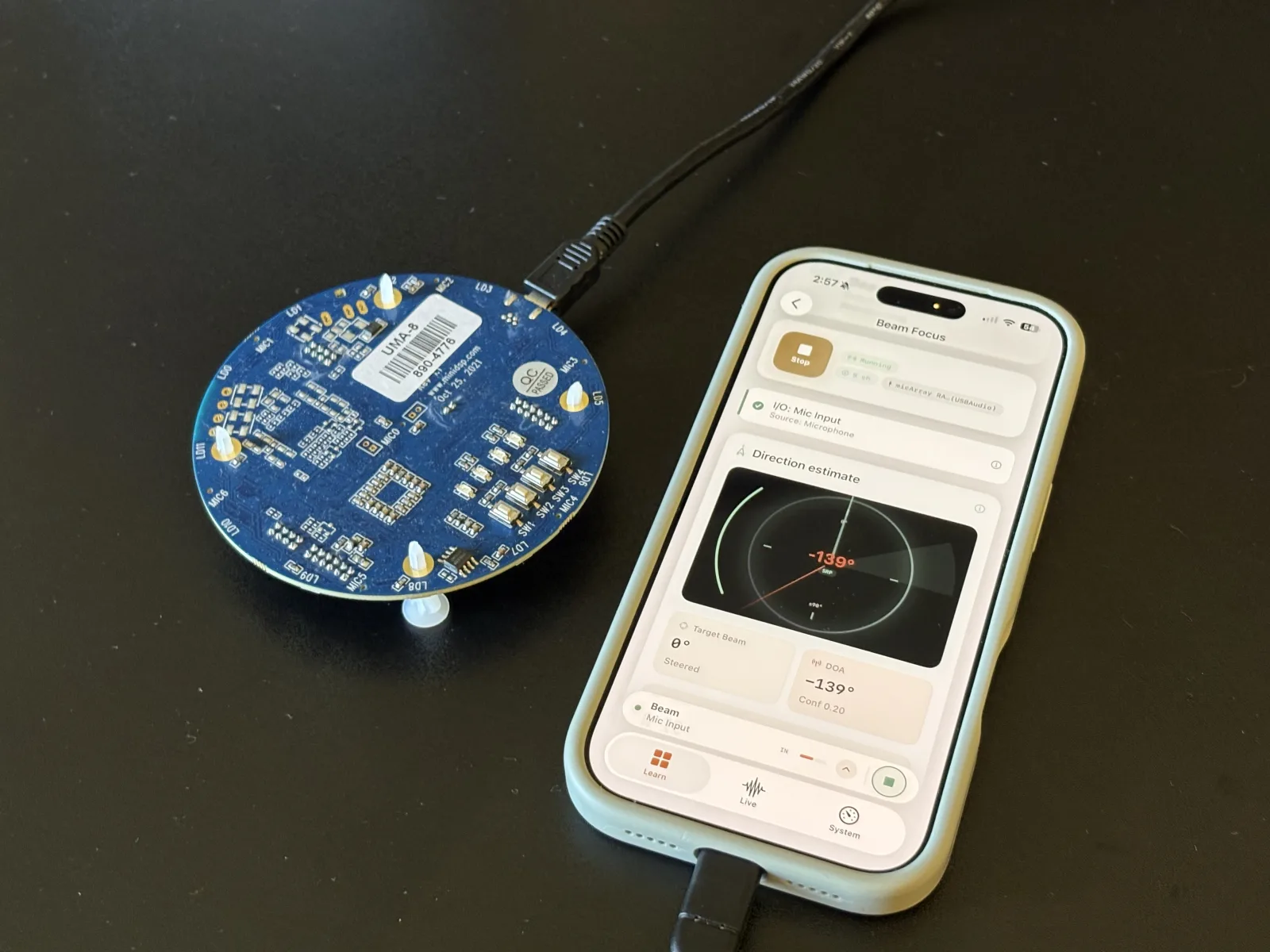
Smart speakers figure out who’s talking and point a listening beam at them using nothing but microphone geometry — no camera, no neural network, just arrival-time physics. This build does the same thing on an iPhone with a miniDSP UMA-8 v2, a compact USB array carrying seven MEMS microphones, and Biquadia, our iOS audio lab. The result is a live compass needle that tracks a talker around the room, a steerable beam that, in our recorded A/B pair, rejects an off-axis talker by at least 13 dB at 2 kHz and 15 dB at 4 kHz (only 1.2 dB if you meter it broadband), and WAV recordings to prove it.
Just as importantly: this post reports what a 44 mm array can’t do, and every hardware gotcha we hit getting USB multichannel audio working on iOS — including a bug that made two unrelated interfaces read exactly 48.16 dB too quiet.
The gear
| Item | Role in this build |
|---|---|
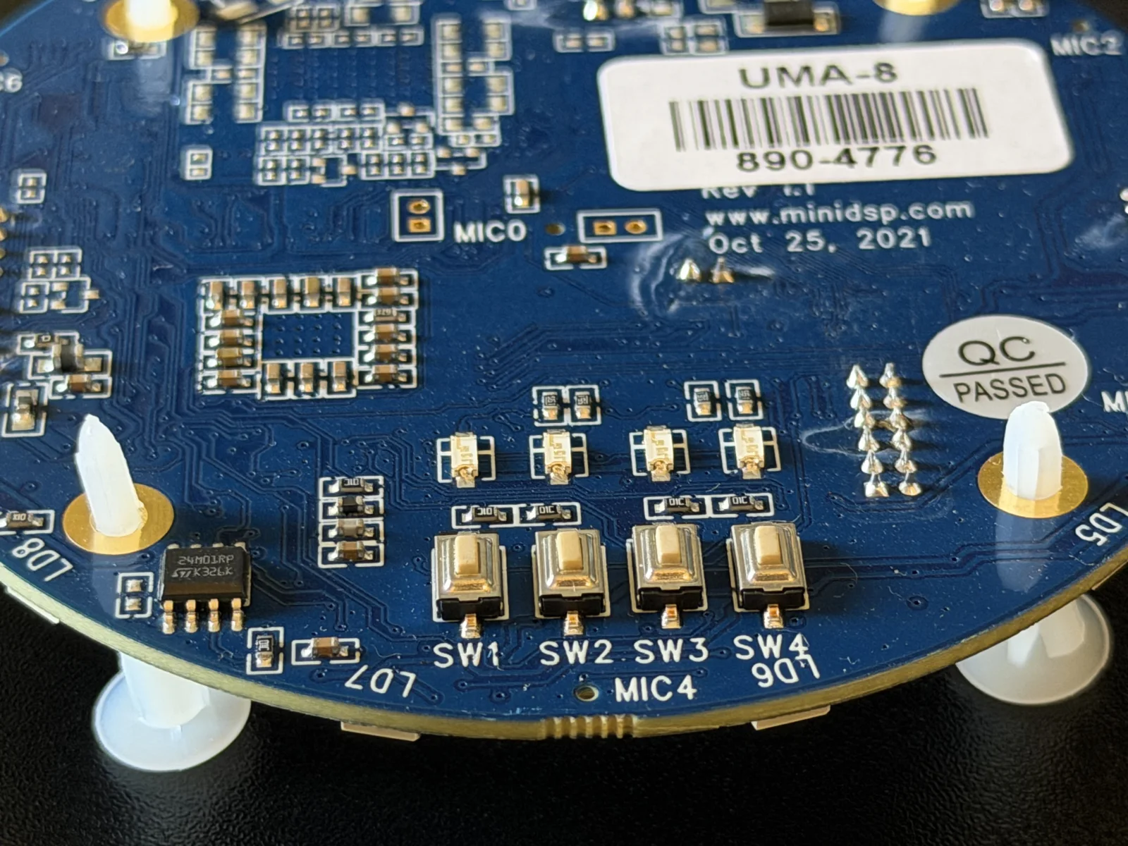
| miniDSP UMA-8 v2 | Seven MEMS capsules — one centre, six on a ring — behind an XMOS USB interface. Flash the raw firmware for 8 discrete channels at 48 kHz. |
| iPhone (USB-C) | Anything running iOS 17+. All numbers in this post were measured on an iPhone 17 Pro. The port speaks USB Audio Class natively — no drivers, no camera adapter. |
| Powered USB-C Hub | Not optional in practice. The UMA-8 is bus-powered and enumerates intermittently on a bare iPhone port; a powered hub fixes it completely. |
| MutecPower 16ft Active USB 3.0 Cable | Repeater cable with active signal booster chipset for long-distance USB audio array runs. |
| MaxLLTo 5V 2A Power Adapter | 3.5mm x 1.35mm DC wall power adapter powering active USB extension repeaters. |
| Biquadia — Audio DSP Lab | The Beam Focus lab: SRP-PHAT direction finding and delay-and-sum / superdirective beamforming over a configurable 2–8 mic geometry. |
How beamforming works in 90 seconds
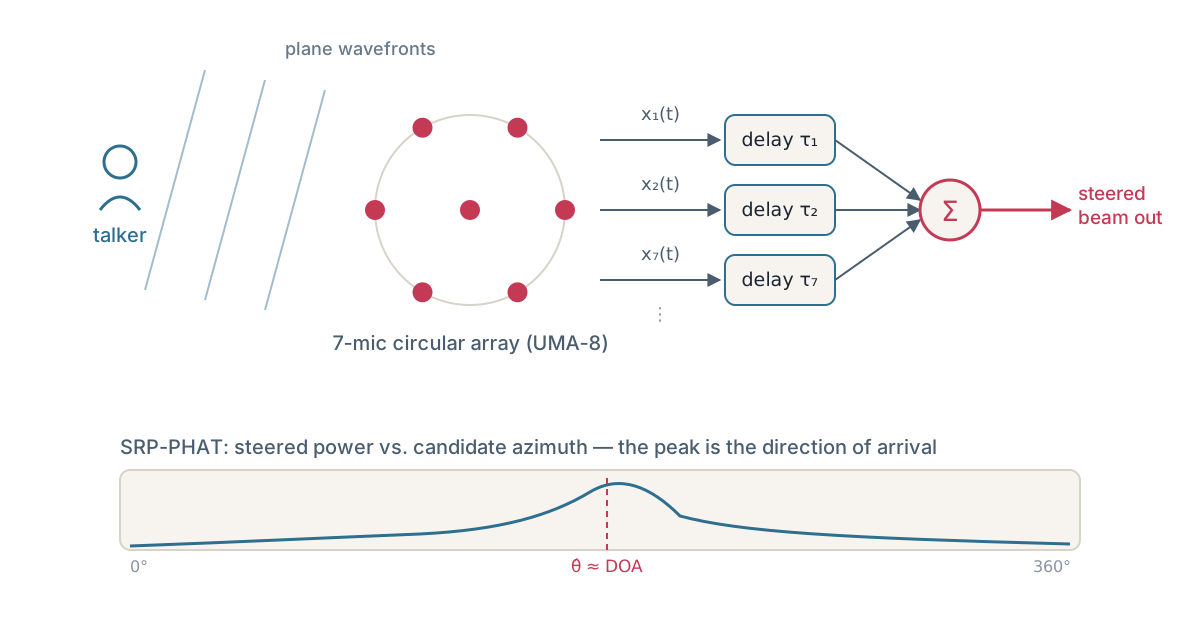
A sound wave from your left reaches the left-most microphone a fraction of a millisecond before the right-most one. At 343 m/s across an 88 mm aperture, that maximum time difference is only ~256 µs — but it’s measurable. Two ideas turn that into an “acoustic camera”:
Direction of arrival (DOA): for every pair of mics, cross-correlate the two signals to find the relative delay. SRP-PHAT (steered response power with phase transform) does this in the frequency domain with the magnitudes whitened away — only phase survives, which makes it robust to loudness and reverberation. Biquadia scans candidate directions in a 5° coarse grid, then refines to 0.25° around the best peaks, integrating over ~170 ms of audio per estimate across all 21 mic pairs.
Beam steering: once you know (or choose) a direction, delay each mic’s signal so that sound from that direction lines up sample-perfectly, then sum. On-axis sound adds coherently; off-axis sound smears. That’s delay-and-sum, the hundred-year-old workhorse.
The catch: on an array only 44 mm in radius, delay-and-sum barely works at speech frequencies. The wavelength at 500 Hz is 69 cm — fifteen times the array radius — so the delays across the array are tiny and the beam is nearly omnidirectional. Measured on this geometry, delay-and-sum has a directivity index of just 0.5 dB at 500 Hz. This is where the third algorithm earns its keep — we’ll get there in the steering section.
Setup: UMA-8 → iPhone
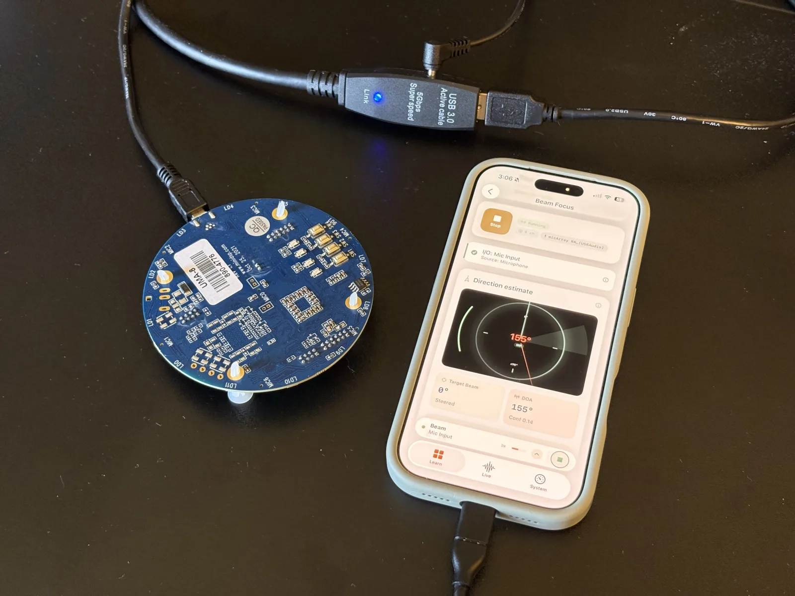
- Flash the raw firmware. Out of the box the miniDSP UMA-8 presents its own onboard beamformer as a processed stereo mix. miniDSP’s firmware utility switches it to raw mode, where it enumerates as
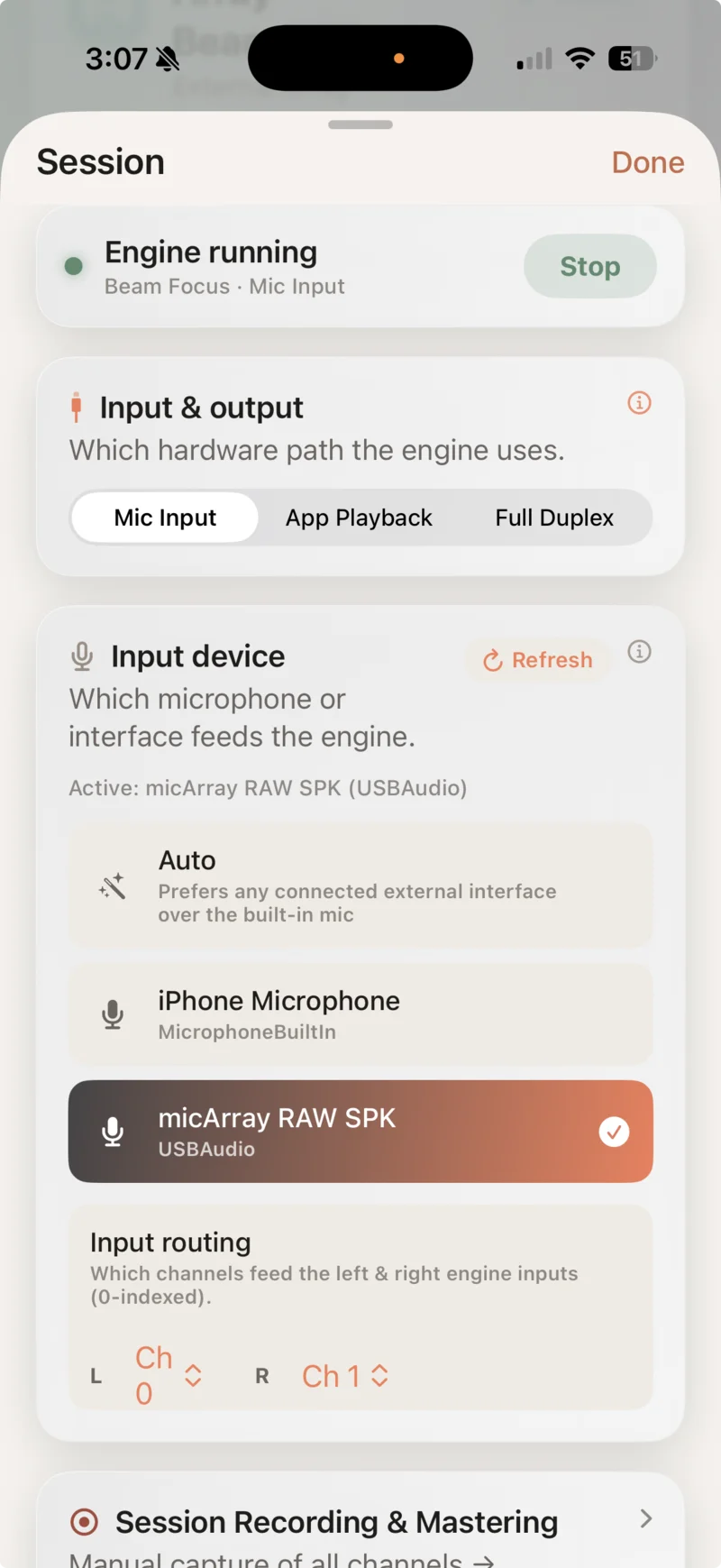
micArray RAW SPK— 8 discrete channels at 48 kHz. Seven carry the MEMS capsules; channel 8 is an unpopulated expansion input and is correctly silent. - Connect through the powered hub. Plug the UMA-8 into a powered USB-C hub and open Biquadia’s Session sheet. Pick the array as the input device; the UMA-8 has no outputs, so the session runs in Mic Input mode. If you need a long bench or room run, pair the MutecPower 16ft Active USB 3.0 Cable with a dedicated MaxLLTo 5V 2A Power Adapter to prevent power dropouts.
- Add +30 dB of input gain. This one surprises everyone: raw MEMS capsules put out roughly −26 dBFS at a loud 94 dB SPL, there is no hardware preamp on the board, and iOS provides no way to set gain on a USB input. Conversational speech at a metre lands near −50 dBFS and looks dead on a meter. Biquadia’s Beam Focus lab has a software input gain slider (0–40 dB, remembered per device) exactly for this — +30 dB is the sweet spot for the UMA-8.
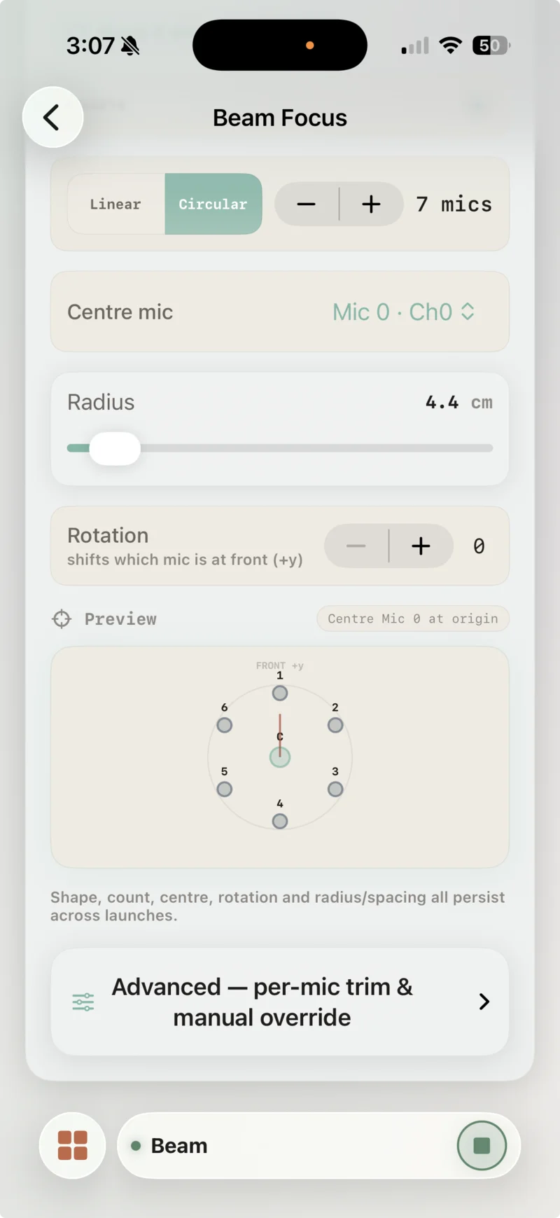
- Check the geometry. Biquadia’s default array preset is the miniDSP UMA-8: 7 mics, centre capsule at the origin, six on the 44 mm ring, channels mapped 0–6 in board order. The geometry card shows
DETECTED INPUTS: 8 chand a live ring preview with the theoretical beam pattern overlaid. If you’re using a different array, the same card lets you place 2–8 mics anywhere within ±30 cm and save it as a preset.
Live direction finding
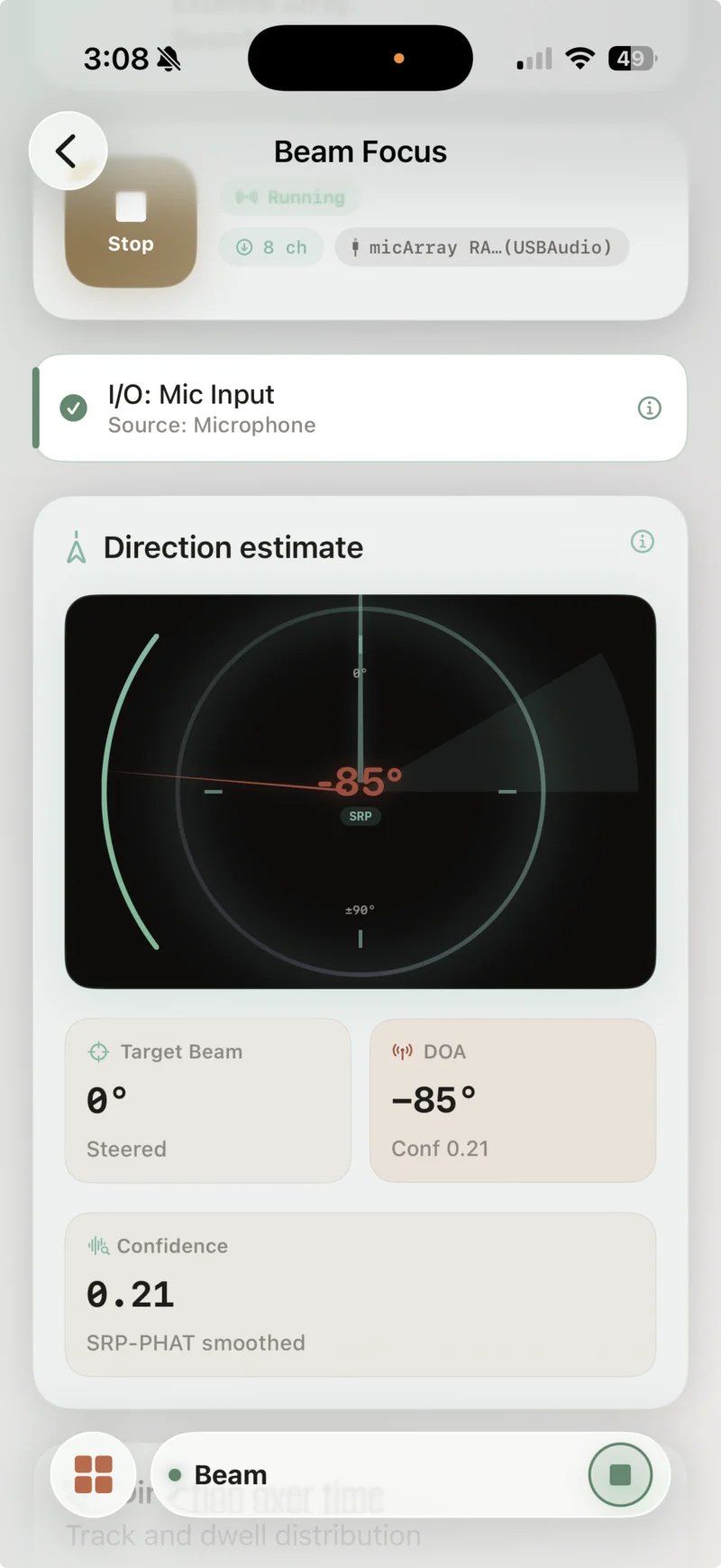
Tap Play and talk. The compass card draws a red needle at the estimated azimuth with the convention 0° = front, +90° = hard right, and a confidence tile under it labelled “SRP-PHAT smoothed.” The estimator publishes about six estimates per second; an exponential smoother tightens or loosens depending on confidence, and below a confidence of 0.10 the needle freezes rather than wander — a gated estimate is displayed as exactly that.
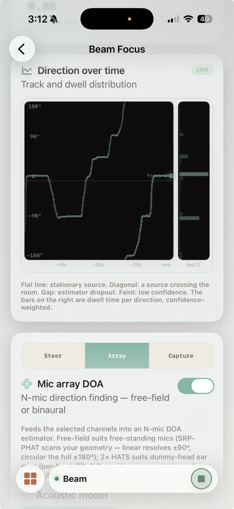
The walk-around is the test that matters: have someone talk while circling the array. A circular geometry resolves the full ±180°, and on the real hardware the needle tracked a talker all the way around the ring at every angle we tried. The “Direction over time” card makes this quantitative — a 60-second azimuth-vs-time strip where a stationary talker draws a flat line, a moving talker draws a diagonal, and a confidence-weighted histogram on the right shows dwell time per direction.
Continuous Azimuth Walk-Around
The direction-over-time card draws the whole walk as one trace: a flat line while the talker stands at 0°, a continuous diagonal down through −90° to the ±180° wrap directly behind the array, then back up through 0° to +90°. No gaps — a gap in this plot is an estimator dropout.
One non-obvious fact for anyone debugging their own array: PHAT weighting is level-invariant. Cranking the input gain makes the meters and the beam louder but does not change DOA confidence at all — only a closer, louder source relative to the room does. If your confidence sits at 0.02 and the needle random-walks, your problem is signal-to-reverberation, not gain.
Steering the beam — and the honest physics
The Steer tab has an algorithm picker with two entries, and the difference between them is the entire story of small-aperture beamforming:
| Directivity index (diffuse field) | 250 Hz | 500 Hz | 1 kHz | 2 kHz | 4 kHz |
|---|---|---|---|---|---|
| Delay & Sum (44 mm ring) | 0.1 dB | 0.5 dB | 1.9 dB | 5.6 dB | 8.7 dB |
| Superdirective (WNG floor −10 dB) | 6.4 dB | 7.8 dB | 10.3 dB | 10.8 dB | 8.8 dB |
Superdirective mode solves the MVDR problem against a modelled diffuse (isotropic) noise field: minimise picked-up room noise subject to passing the look direction untouched. On a small array that optimisation wants to amplify tiny inter-mic differences — the unconstrained solution at 500 Hz would boost microphone self-noise by 34 dB, which is unusable outside a simulator. The fix is a white-noise-gain constraint: a “robustness floor” slider (−20 to 0 dB, default −10 dB) that caps how much the design may amplify self-noise and gain mismatch in exchange for directivity. That constraint isn’t an advanced option — it’s the reason the feature works on real hardware.
The design is realised as a 513-tap linear-phase FIR per mic (group delay 5.3 ms at 48 kHz), recomputed in ~80–120 ms on a background thread whenever you move the slider, and run through an overlap-save FFT path — total load is about a fifth of real time on the phone. Below 150 Hz the design blends back to pure delay-and-sum, because down there the maths would be all self-noise amplification and no directivity.
The UI reports the designed directivity index live in five bands, and the app’s own footer states the limit better than we can: a 44 mm ring cannot beat physics — expect roughly 6–10 dB of diffuse-field rejection through the speech band, delay-and-sum behaviour below 150 Hz, and less than the designed numbers once room reverberation dominates beyond the critical distance.
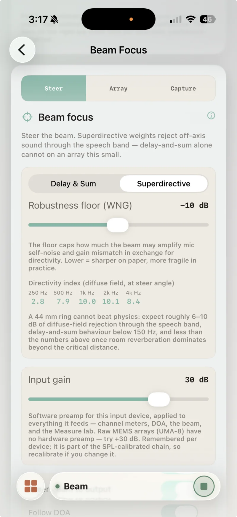
Live Five-Band Directivity Readout
The Steer tab displays live directivity index numbers computed directly from the active 513-tap FIR filter design. With the White-Noise-Gain (WNG) robustness floor set to −10 dB, the design achieves 6.4, 7.8, 10.3, 10.8, and 8.8 dB across the 250 Hz – 4 kHz speech bands.
A repeatable A/B test
“The beam sounds tighter” is not a measurement. Here’s the protocol we use; it takes five minutes and produces WAV files you can level-meter:
- Input gain ≈ +30 dB; confirm the compass tracks you around the array first (that validates geometry and channel mapping in one move).
- Turn Follow DOA off and fix Beam Direction at 0°. (Our first A/B was garbage because the beam was steering itself toward a low-confidence random walk — fix the beam, then test.)
- In Superdirective mode, record ~5 s of speech from 0° at 0.5 m, then ~5 s from 135° at the same distance and level.
- Repeat both takes in Delay & Sum.
- Meter the results per octave band, not broadband. This is the step everyone skips and it is the one that decides whether your A/B reads as a result or as nothing at all. The clips below differ by 1.2 dB broadband and by more than 13 dB at 2 kHz — the broadband number is not a smaller version of the truth, it is the answer to a different question.
Expected result in a live room at conversational distance: 6–12 dB on-axis vs off-axis difference in Superdirective, ~1–3 dB in Delay & Sum. The gap between the two algorithms is the honest, reproducible result — and hearing the same room collapse around one voice when you switch modes is the moment this stops being abstract.
Listen to one such pair, both takes recorded in Superdirective mode with the beam fixed at 0°. The same +21 dB of playback gain is applied to both clips — the raw captures peak at −24 dBFS and are close to inaudible on laptop speakers — so the difference you hear between them is the one the beamformer produced, not one we introduced. The raw WAVs are linked under each player if you’d rather meter them than trust us.
On-Axis (0°, High SNR)
Target talker aligned with the steered beam.
raw: −24.5 dBFS peak · −40.0 dBFS speech RMS · WAV
Off-Axis (−90°, Attenuated)
Off-axis talker rejected by superdirective MVDR beamforming.
raw: −30.3 dBFS peak · −41.2 dBFS speech RMS · WAV
Now measure them, because this pair is a good lesson in choosing the right statistic. Level-meter the two raw WAVs broadband and you get 1.2 dB of difference, which would suggest the beamformer is doing almost nothing. That number is wrong — not arithmetically, but as a comparator. The talker here is whispering at about two feet, the capture noise floor is broadband, and a broadband average is therefore mostly a measurement of the room. Split it into the same octave bands as the directivity table, subtract the noise power from the speech-active power in each band, and the beam reappears:
| Octave band | On-axis SNR | Off-axis SNR | Rejection at −90° |
|---|---|---|---|
| 250 Hz | 6.2 dB | 5.6 dB | 1.9 – 2.6 dB |
| 500 Hz | 6.2 dB | 5.0 dB | 0.7 – 1.4 dB |
| 1 kHz | 7.7 dB | 3.6 dB | not resolvable (−1.4 to +2.8 dB) |
| 2 kHz | 16.8 dB | 1.8 dB | ≥ 13 dB (floor-limited) |
| 4 kHz | 21.3 dB | 1.5 dB | ≥ 15 dB (floor-limited) |
Speech-active = loudest 10% of 20 ms frames, selected on the 300–3400 Hz envelope so the choice isn't driven by low-frequency rumble. Ranges span every combination of 5/10/20% active and noise windows. The two upper bands are quoted as lower bounds because off-axis they sit under 2 dB above the noise floor — the rejection is at least this large, and the floor prevents us saying how much larger.
These are not the same quantity as the directivity indices earlier in the post, and they are allowed to be larger. Directivity index is a diffuse-field average — rejection averaged over every direction at once. This table is rejection at one direction, −90°, where the beam pattern can have a genuine null. A design with a 10.8 dB DI at 2 kHz can easily be 20 dB down at one unlucky angle and 3 dB down at another; the average is what the DI reports. If you want the number that predicts how much room noise disappears, use the DI. If you want the number that predicts what happens to the one person talking from over there, use this one.
Two things make this the honest read rather than a flattering one. The upper-band numbers are bounds, not point estimates: off-axis at 2–4 kHz the whisper has been pushed into the noise, so the true rejection is somewhere past 13–15 dB and this recording cannot say where. And the low bands double as an internal control — if the talker had simply been quieter on the second take, every band would have dropped together. They don’t: 250 and 500 Hz match within about 2 dB while 2 and 4 kHz collapse. A frequency-dependent difference on takes of comparable vocal effort is a beam pattern, not a level change.
It also explains why the difference is so obvious to the ear despite that 1.2 dB broadband figure. Whispered speech has no voicing to put energy down low; it is almost entirely turbulent fricative and sibilant noise between roughly 2 and 8 kHz — precisely the bands where the array has enough aperture to form a deep null, and precisely the bands carrying the intelligibility. At 4 kHz the wavelength is 8.6 cm, comparable to the 88 mm aperture. At 500 Hz it is 69 cm, and the array is nearly blind to direction, which is the same physics that gives delay-and-sum its 0.5 dB directivity index in the table above. The beam does not attenuate this talker uniformly. It removes the part of them you were using to understand the words.
Recording, and getting the audio off the phone
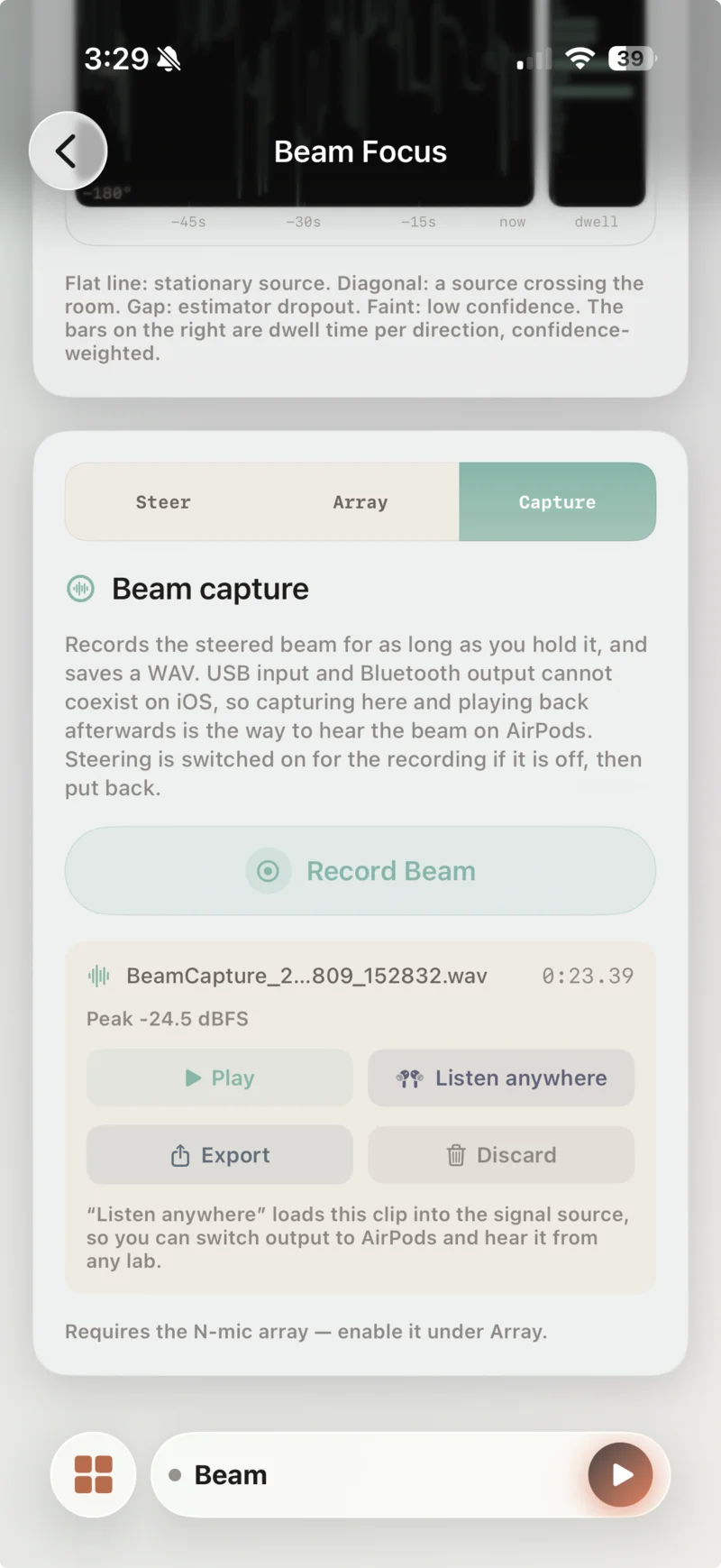
Peak Level Readout & "Listen Anywhere"
Captures the steered mono beam to 16-bit 48 kHz WAV format with immediate peak dBFS feedback. The "Listen anywhere" feature allows playback on AirPods or speakers by loading the clip into signal memory after unplugging the USB array.
Three recorders cover the beam workflow:
- Beam capture — the steered mono beam, written to
Documents/BeamCaptures/as 16-bit 48 kHz WAV, with a live peak readout so an accidentally-silent take is caught immediately. - Raw array recording — all 7 channels as a single multichannel WAV, for offline processing in Python or MATLAB.
- Session capture — a folder with input/output/mastered WAVs plus a
manifest.jsonthat snapshots the array geometry, so a recording is re-beamformable offline months later.
Why “capture then play”? Because USB audio input and Bluetooth output cannot coexist on iOS — the route arbiter tears the pair down in every session mode (we proved this across 15 configurations before accepting it). While the UMA-8 is connected you cannot monitor live on AirPods, period. So the Capture tab’s “Listen anywhere” button loads your take into the app’s signal source; unplug or switch output, and audition the beam on anything.
Gotchas: what USB multichannel audio on iOS is actually like
Everything above works today, but four discoveries cost us real bench time, and anyone building with USB arrays on iOS will hit some of them:
- The 48.16 dB bug. USB audio devices commonly deliver 24 valid bits in a 32-bit container. Normalise by the container (2³¹) instead of the valid bits (2²³) and every sample comes out 256× — exactly 48.16 dB — too quiet. It presents as a hardware fault: dead meters, an SPL meter reading nothing, DOA confidence of 0.01. What ruled out hardware for us was that a Behringer UMC1820 audio interface and the miniDSP UMA-8 — two unrelated devices — were identically wrong. When two different devices fail the same way, suspect the shared code path.
- Channel identity isn’t guaranteed. On iOS 26.5 the UMA-8’s stream arrived with a channel-description layout that a mixer node silently re-interpreted, leaving channels 0–1 empty and the signal shifted into 2–6. If your first and last mics look dead but the middle ones work, you’re looking at a channel-layout conversion, not broken capsules.
- Bus power is marginal. Bare iPhone port: intermittent enumeration, occasional total drop-off. A powered USB-C hub fixes it completely. Budget the $20.
- MEMS levels are just low. −26 dBFS at 94 dB SPL, no preamp, and iOS can’t set USB gain. Software makeup gain is the correct fix; it belongs at the capture entry point so meters, DOA, SPL and the beam all agree.
Build it yourself
Biquadia runs the whole lab in this post — SRP-PHAT direction finding, superdirective beamforming, and calibrated measurement — 100% on-device, on the phone already in your pocket. The N-mic array is part of Biquadia Pro ($4.99/month with a 7-day free trial, or $79.99 lifetime); two-mic GCC-PHAT direction finding works in the free tier, so you can validate a stereo setup before committing.
Next in this series: we put a binaural dummy head, a Behringer UMC1820 audio interface, and a multimeter to work measuring Sennheiser HD 650s — absolute-SPL calibrated, from the same phone.
FAQ
Can an iPhone really do real-time beamforming?
Yes, with headroom. Processing seven 48 kHz channels through SRP-PHAT direction finding plus a 513-tap-per-mic superdirective FIR beamformer runs at a real-time factor of roughly 0.2 on an iPhone 17 Pro — about a fifth of one core's real-time budget — because the convolution runs as overlap-save FFTs rather than time-domain multiply-accumulates.
Does the miniDSP UMA-8 work with an iPhone?
Yes. In raw 8-channel firmware mode the UMA-8 is a class-compliant USB audio device; iOS enumerates it as 'micArray RAW SPK' with 8 channels at 48 kHz (7 populated microphone channels) and needs no drivers. Two caveats: it is bus-powered, so use a powered USB-C hub, and iOS caps this capture path at 16-bit — about 14 effective bits measured, which only matters below −60 dBFS.
Do I need a powered USB hub for the UMA-8?
Strongly recommended. The UMA-8 is bus-powered, and on a bare iPhone USB-C port it can enumerate intermittently or drop off entirely, leaving iOS reporting only the built-in microphone. Through a powered USB-C hub, enumeration is reliable.
Can I listen to the beam on AirPods while the UMA-8 is connected?
Not live. iOS tears down any USB-audio-input plus Bluetooth-output combination in every session mode — we verified this across 15 route configurations before accepting it. The workaround is built into the workflow: record the steered beam to a WAV, then load the clip as the signal source and switch output to AirPods for playback.
What beamforming algorithms does Biquadia use?
SRP-PHAT for direction of arrival over a configurable 2–8 mic geometry; delay-and-sum steering; and a white-noise-gain-constrained superdirective beamformer (MVDR against a modeled diffuse field) realised as 513-tap linear-phase FIRs per mic. A separate true covariance MVDR path exists for 2-mic stereo input.
My beamformer A/B test shows almost no difference. What am I doing wrong?
Most likely you are metering broadband. On a small array the rejection is strongly frequency-dependent, and a broadband RMS average is dominated by the low-frequency bands where a 44 mm ring is nearly blind to direction. Our own published A/B pair differs by only 1.2 dB broadband, but by at least 13 dB at 2 kHz and at least 15 dB at 4 kHz once you split it into octave bands and subtract the noise power from the speech-active power in each. Also check that the off-axis take has not simply fallen into the noise floor — if the quiet clip sits under about 2 dB above its own floor in a band, that band gives you a lower bound on rejection, not a measurement of it.
How much noise rejection can a 44 mm microphone array actually achieve?
Physics caps a ring this small: expect roughly 6–10 dB of diffuse-field rejection through the speech band in superdirective mode, delay-and-sum behaviour below about 150 Hz, and less once room reverberation dominates beyond the critical distance. Plain delay-and-sum manages only about 0.5 dB of directivity at 500 Hz on this aperture. If a product listing promises dramatically more from a device this size, be suspicious.
Gear for this post
Affiliate linksPicked for this post by its author. Product images and prices come from the Amazon Creators API and SparkFun.
 $105Microphone
miniDSP UMA-8 USB Microphone Array
7-element MEMS microphone array with onboard XMOS DSP for raw channel output and real-time spatial audio / beamforming research.
 $229.00Audio interface
Behringer UMC1820 Audiophile 18x20 USB Audio/MIDI Interface with Midas Mic Preamplifiers and ADAT I/O | For Recording Microphones and Instruments
Audio interface used building Biquadia — 8-preamp USB I/O for real-time DSP testing.
 $38.99Accessory
USB C Docking Station Dual DisplayPort, 8 in 1 USB Hub with 2 DP, HDMI, VGA, USB C 2.0, A 2.0, PD Charging Port, Multi Monitor Adapter for Dell/HP/Lenovo Laptops
Studio desk dock used across all app development work.
 $29.99Cable
MutecPower 16 Feet Active USB Extension Cable 3.0 Male to Female with A Extension chipset Signal Booster - Active Extension/Repeater Cord 5 Meters / 16 Feet
Active USB 3.0 extension cable with signal booster chipset for long-distance USB audio array runs.
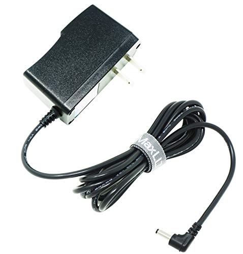 $11.99Power
MaxLLTo 5V 2A AC Power Adapter with 3.5mm x 1.35mm Connector Plug, Wall Charger Power Adaptor for Tablets, Wireless Router, Switches, USB Hubs, Android TV Box, CCTV IP Cameras, LED Strip Light
5V 2A DC wall power adapter powering active USB extension repeaters and audio hardware.
 $149.95Microphone
miniDSP UMIK-1 Calibrated Measurement Microphone
Calibrated USB mic with individual cal file — measure your room's RT60 and modal peaks to validate the room-mode eigenfrequencies this calculator predicts.
Prices shown were retrieved from the Amazon Product Advertising API on 8 October 2026 and are indicative only — the price and availability on Amazon at the time of purchase apply.
Prices shown were each checked against the Amazon product listing between 8 August 2026 and 17 September 2026 and are indicative only — the price and availability on Amazon at the time of purchase apply.