Hardware build / Measurement
Calibrated Multichannel & Binaural Audio Recording on iPhone
Measure headphones with a binaural dummy head and an iPhone: SR3D head, class-compliant USB interface, and a loaded 1.00 V / 1 kHz reference to dB SPL.

Joshua HriskoPrincipal Engineer
11 min readSan Francisco, CA
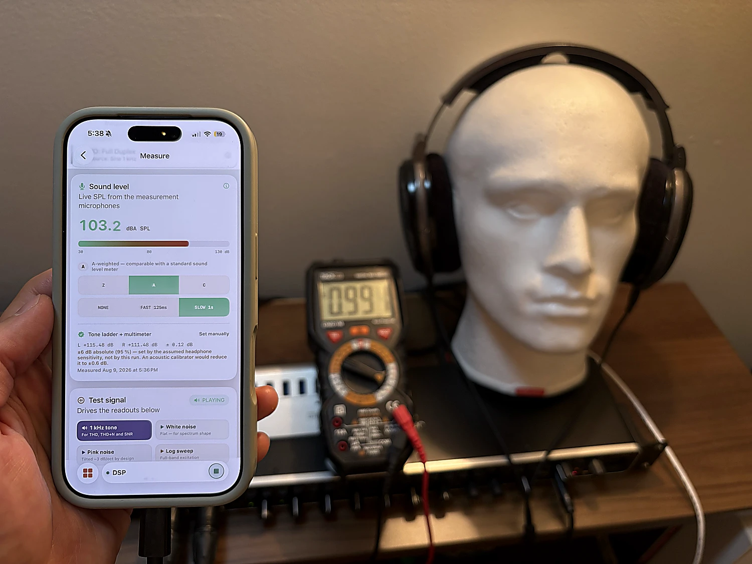
Commercial head-and-torso simulators (HATS) — the mannequins behind many headphone-review charts — cost as much as a car. This build is a practical binaural-dummy-head alternative: a SR3D® Dummy Head MKIII with microphones in its ears, a Behringer UMC1820 class-compliant interface, the Sennheiser HD 650 under test, and a true-RMS multimeter whose AC-voltage bandwidth covers 1 kHz (the Fluke 87V is one suitable option). The electrically referenced 1 kHz calibration, THD analysis, and level display run entirely on an iPhone in Biquadia’s Measure lab.
The anchor is simple: Sennheiser specifies the HD 650’s nominal output as 103 dB SPL at 1 kHz for 1.00 V RMS. Measuring that voltage across the loaded headphone terminals gives this particular capture chain a repeatable reference. It does not prove that this particular driver, seal, and ear geometry produce exactly 103 dB; those factors set the method’s absolute uncertainty.
The gear
| Item | Role in this build |
|---|---|
| SR3D® Dummy Head MKIII | A binaural head with silicone pinnae and a Primo EM272 electret capsule seated in each ear canal. The ears are the measurement microphones. |
| Behringer UMC1820 | Class-compliant USB interface — this direct 48 kHz connection exposes 10 inputs and 12 outputs to iOS with no vendor driver. It drives the headphones and captures both ears simultaneously. |
| Sennheiser HD 650 (official specifications PDF) | The headphone under test: nominally 300 Ω and 103 dB SPL at 1 kHz for 1 V RMS. The same specification appears on printed page 5 of this Sennheiser HD 650 manual mirror. |
| Fluke 87V True-RMS Multimeter | A suitable high-end meter for the electrical reference. Use a meter with documented AC-voltage accuracy at 1 kHz; true-RMS capability alone does not guarantee enough bandwidth. Expect ~1.00 V for the nominal 103 dB reference or ~0.27 V for 91.6 dB. |
| HOSONGIN 1/4″ TRS Y-Splitter Cable | Lets the meter read the headphone terminals while the HD 650 stays plugged in and on the head — the voltage under load is the one that matters. |
| Biquadia — Audio DSP Lab | Calibration wizard, dual-ear level monitoring, and calibrated SPL meter — 100% on-device on iPhone. |
Why a dummy head
You can’t measure a headphone by pointing a microphone at it. A headphone’s response only exists against an ear: the pad seal sets the bass, the pinna and ear canal impose resonances worth 10–15 dB in the treble, and the left and right cups seal differently on any real geometry. A binaural head reproduces that acoustic load — which is why lab measurements use ear simulators, and why this rig puts a capsule at the entrance of each silicone ear canal rather than on a mic stand.
The SR3D is a binaural dummy head, not a standardized HATS or an IEC ear simulator. That distinction matters: it preserves a realistic, repeatable fixture for this head and these pads, but it does not make its absolute response interchangeable with an industry-standard coupler.
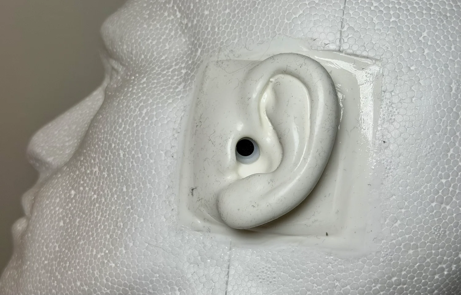
The consequence worth internalizing: the two ears are genuinely different instruments. Different pinna castings, different capsules, different seal. Biquadia therefore runs a completely independent analyzer per ear and never mixes them to mono — summing two coherent-but-different responses would comb-filter the result and invent nulls present in neither ear. Every result in this post is a pair.
Wiring the chain (and an iOS gotcha)
There are two directional routes, plus one observation point: playback is iPhone → USB-C host cable/adapter → UMC1820 DAC and phones amp → HOSONGIN 1/4” TRS Y-splitter → HD 650; capture is ear canal → EM272 capsule → UMC1820 preamp and ADC → iPhone. The meter observes one loaded headphone channel at the splitter; it is not in the audio path. Concretely:
- HD 650 into the MAIN phones output of the Behringer UMC1820 — not an auxiliary output pair. In this tested iOS route, playback arrived on USB output channels 1–2; attempts to target higher output pairs were silent. Biquadia therefore drives the main pair and says so on screen. Use the main jack unless your own interface-and-app combination proves a different mapping.
- Left ear mic → input 1, right ear mic → input 2. The Session sheet’s input-routing picker maps any hardware channel to either engine input, so nothing breaks if your rig is wired differently — but 1/2 is the convention the wizard’s checklist assumes.
- Lock both gains. The calibration describes one unchanging chain: mic-preamp gain and phones-output level. Moving either control afterwards silently invalidates the fitted offset. Mark the knob positions with tape.
- I/O mode: Full Duplex. Measurement plays a signal out and captures the response simultaneously. Biquadia’s Measure lab checks this and offers a one-tap “Switch to Full Duplex” fix if the session is in a mic-only or playback-only mode.
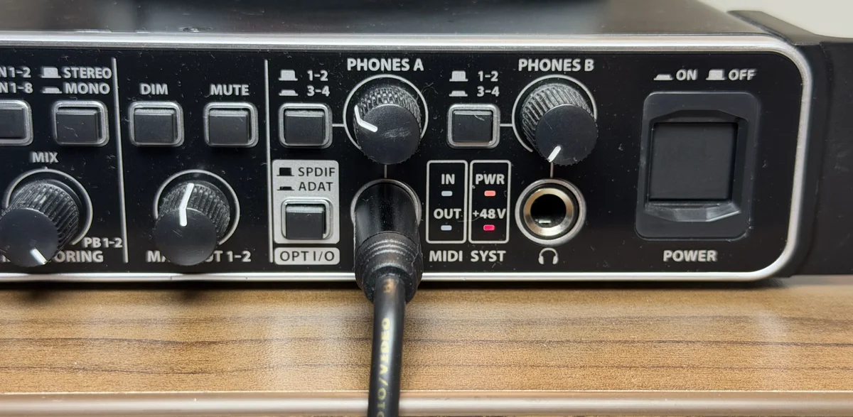
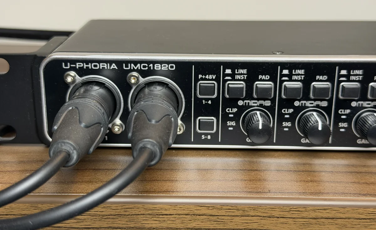
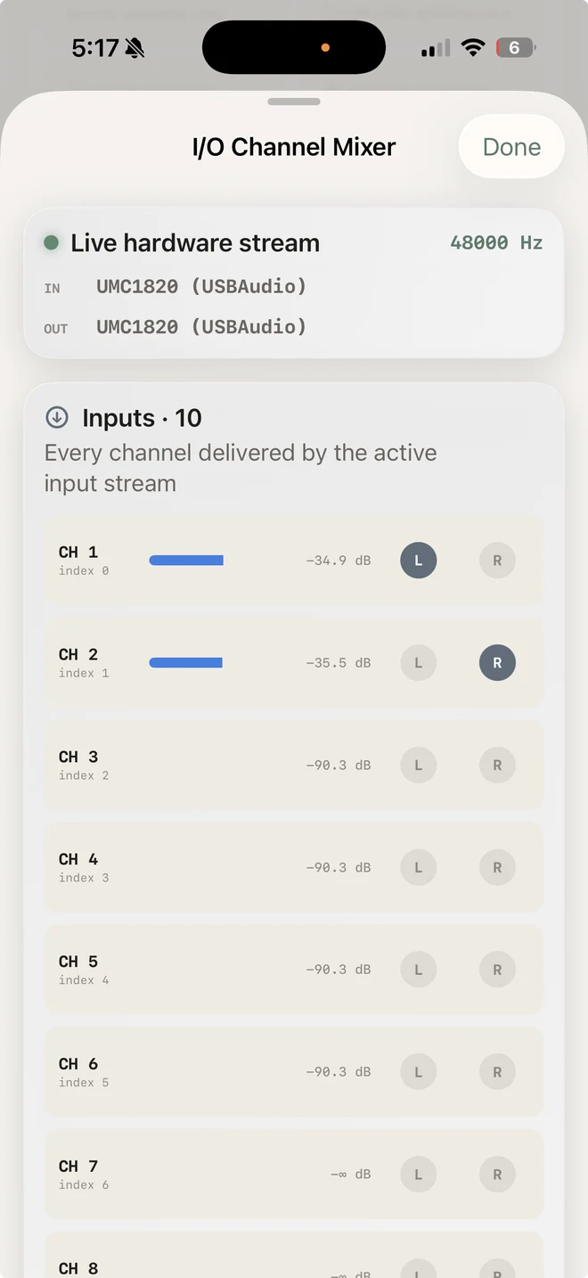
The I/O Channel Mixer (System tab) is the rig’s truth panel: all 10 input channels with live peak meters. Ear mics on 0–1 showing active signal, open preamps idling near −90 dBFS, unconnected S/PDIF channels silent. Thirty seconds here confirms the whole capture side before you measure anything.
Spatial Binaural Auditioning: Voice Walkaround
SR3D DUMMY-HEAD CAPTUREA voice begins center-front, moves to the right ear, crosses to the left, then returns to center-front. The capture has a +26 dB gain raise applied equally to both ears, so the interaural level differences survive intact; start at a low volume, then wear headphones to experience the spatial pinna transfer function.
The 1 V at 1 kHz = 103 dB SPL nominal reference
The interface reports relative dBFS (decibels relative to digital full scale). That number alone says nothing about pressure at an ear-canal microphone. The meter does not measure pressure directly; it ties a known 1 kHz voltage at the loaded headphone terminals to Sennheiser’s stated sensitivity, while the ear capsules record the corresponding digital level. That creates an indicated dB SPL reference for this fixed chain.
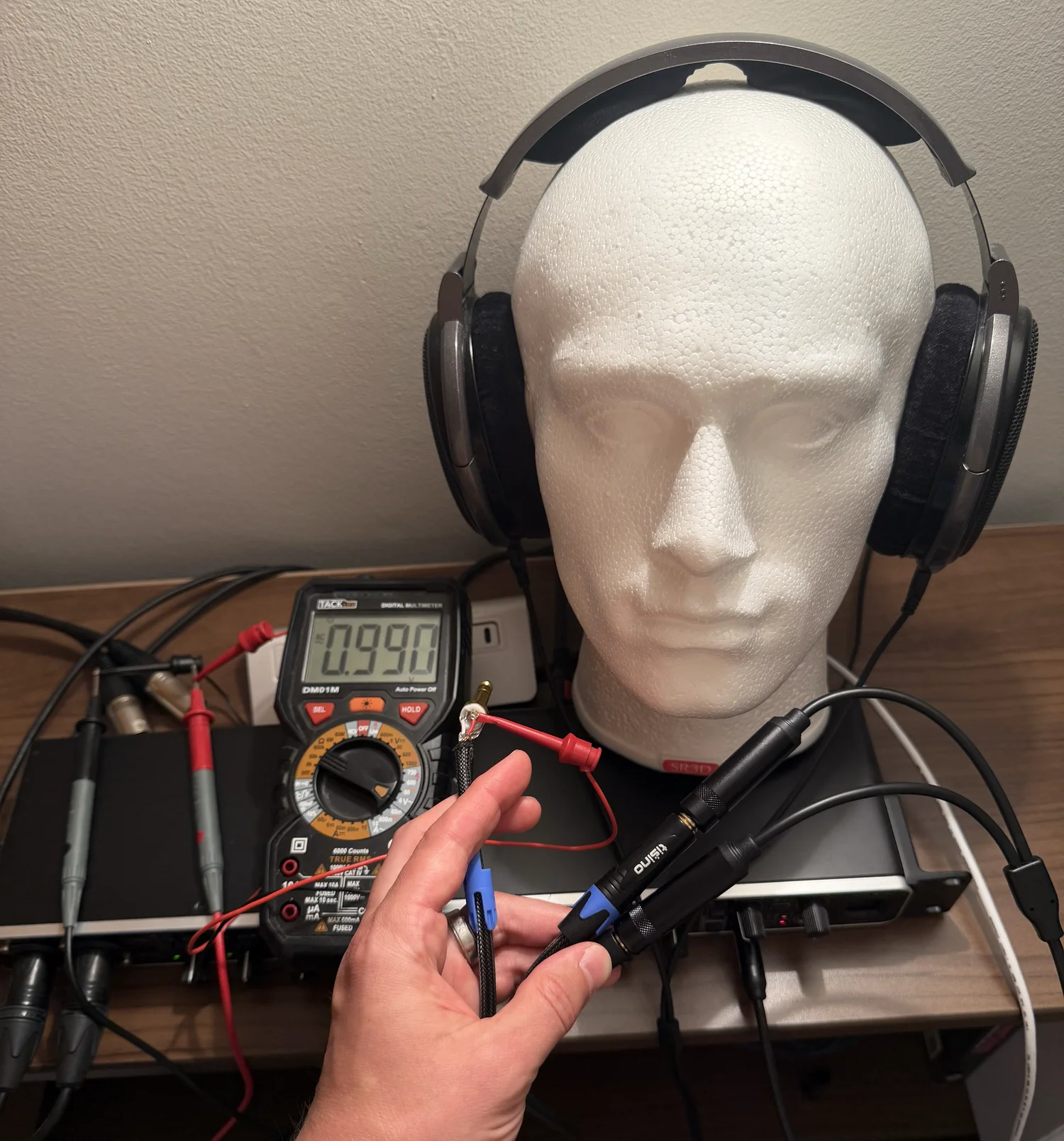
Sennheiser specifies the HD 650 at 103 dB SPL for 1.00 V RMS at 1 kHz, with a nominal impedance of 300 Ω. That value appears in Sennheiser’s current official specifications PDF and on printed page 5 of the legacy HD 650 manual mirrored by B&H. Adjust the generator or interface volume until a suitable true-RMS meter (such as the Fluke 87V) reads 1.00 V RMS across a loaded channel while the 1 kHz sine plays. Verify tip-to-sleeve and ring-to-sleeve once during setup; a single reading does not prove that both amplifier channels track identically. The resulting 103 dB SPL is the manufacturer’s nominal reference, not a fresh acoustic measurement of this individual driver, pad seal, or dummy ear.
At 1 kHz, voltage scaling is valid while the electronics and driver remain linear. Writing the voltage ratio explicitly keeps the logarithm dimensionless:
Here is the level stated at the 1 V RMS, 1 kHz reference condition—not a quantity with units of dB/V. If is entered numerically in volts, the common shorthand is ; its hidden denominator is 1 V.
For the HD 650 at 1 kHz:
- At , nominal.
- At , nominal.
- At the photographed , nominal.
For each ear, Biquadia compares that nominal reference with the simultaneously captured 1 kHz RMS level in dBFS, using the same measurement window for every tone rung:
As long as the phones-output level, preamp gain, and routing stay unchanged, produces a repeatable, electrically referenced 1 kHz indication. The six-rung ladder tests whether the transfer is linear and reports the residual fit; it cannot remove uncertainty in HD 650 unit sensitivity, pad seal, dummy-ear geometry, or microphone response. Its internal fit is therefore distinct from Biquadia’s wider ±6 dB absolute (95%) method estimate. A scalar 1 kHz offset does not make a broadband or weighted level traceable: away from 1 kHz, capsule and fixture response dominate until they are acoustically calibrated or compensated.
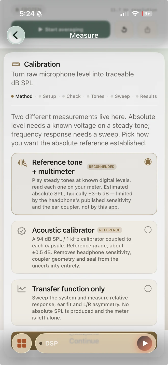
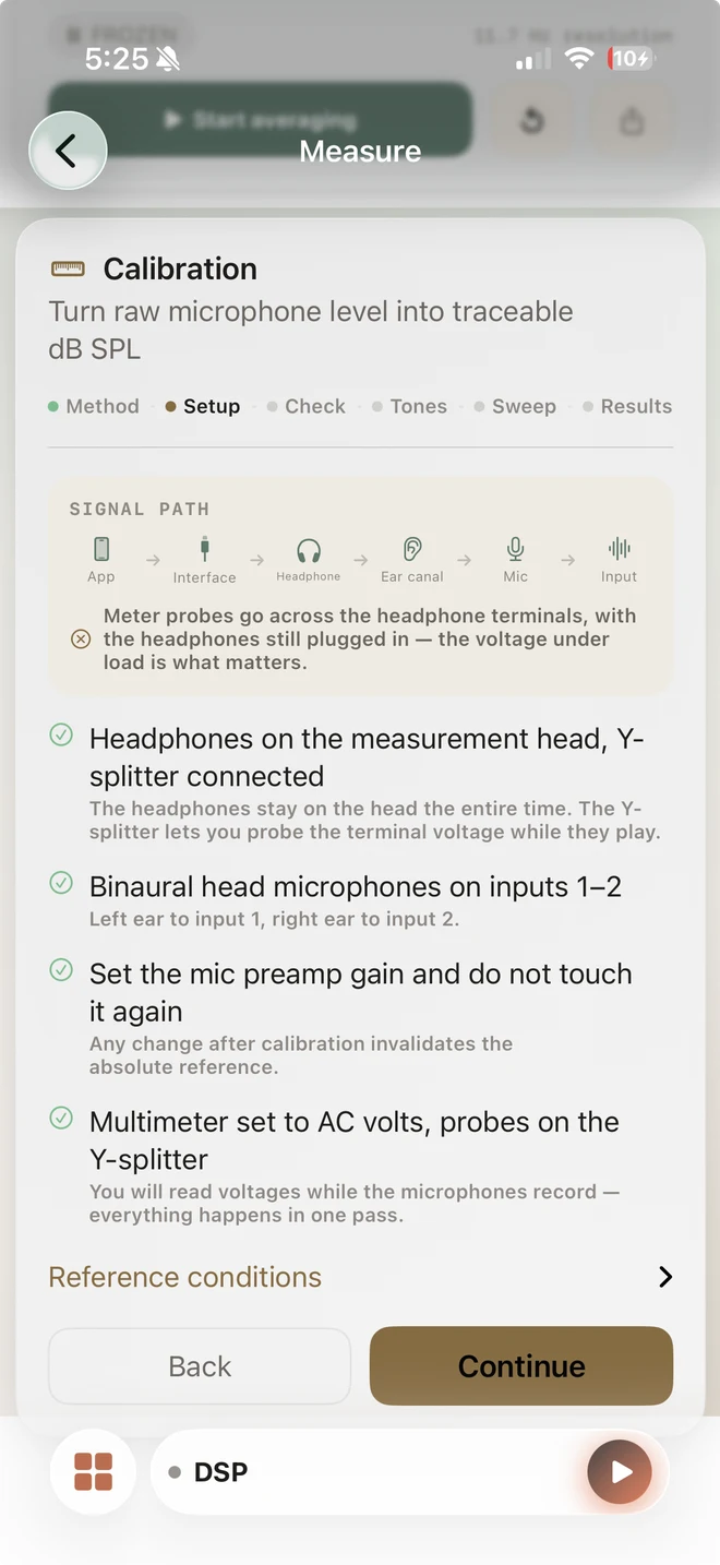
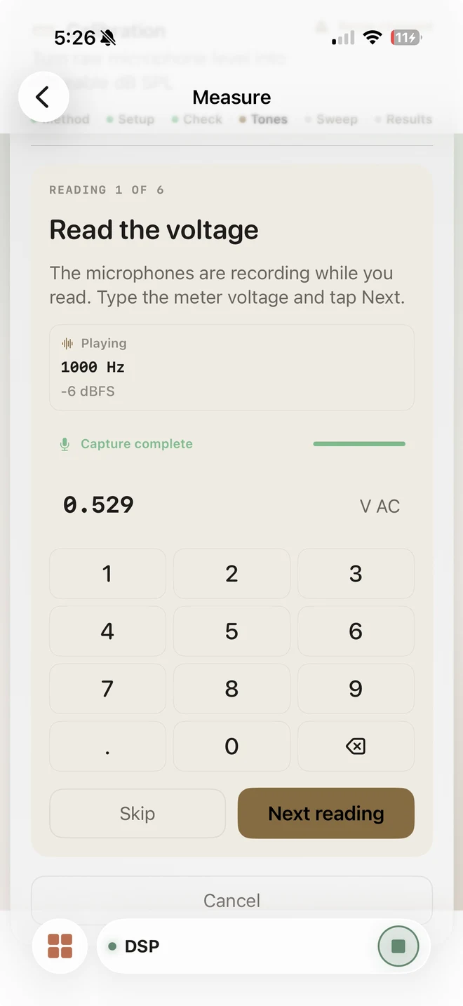
The calibration wizard walks through this step by step:
- Method selection: Pick “Reference tone + multimeter” for a binaural head whose permanently mounted capsules cannot accept an acoustic calibrator.
- Setup lock: Confirm the loaded headphone path, left/right input assignment, fixed preamp and phones-output gains, and AC meter probe placement before recording.
- Tone ladder & voltage entry: Play six 1 kHz reference tones, enter the measured loaded AC RMS voltage for each rung, and use the simultaneous ear captures to test linearity and calculate fit residual.
- Independent ear offsets: Biquadia solves each ear separately. The photographed run produced L +115.48 dB / R +111.48 dB, with a ±0.12 dB internal-fit figure and a separate ±6 dB absolute (95%) method estimate.
Live PIP calibration demonstration
The Biquadia wizard runs the 1 kHz reference ladder on the SR3D + HD 650 rig, with the Fluke 87V visible in the picture-in-picture overlay.
What this calibration supports
With the chain locked, the SR3D dummy head and Biquadia become a practical binaural measurement suite. The calibration adds a declared 1 kHz reference; it does not alter the underlying recordings or turn this fixture into a standards-grade sound-level meter.
- Level monitoring (dBZ / dBA / dBC): Display real-time, electrically referenced indicated level at the ear-canal capsules with Z, A, or C weighting and Fast/Slow time constants. The weighting filters are DSP; without a capsule/fixture response calibration, their broadband absolute result is not an IEC 61672 claim.
- Harmonic distortion and THD: Play 1 kHz test tones and inspect harmonics 2–10, THD+N, SNR, and electrically referenced ear-canal noise floor. The result belongs to the complete playback-and-capture chain—DAC, amplifier, HD 650, seal, microphones, and ADC—not to the headphone driver alone.
- Binaural headphone capture: Record paired 48 kHz WAV signals directly from the ear capsules for A/B comparison and spatial auditioning. The files retain their native left/right transfer functions; do not sum them to mono, which can introduce comb filtering.
Gotchas
- The exact-zero USB input. Twice on this rig, the Behringer UMC1820 enumerated, negotiated all 10 channels, and delivered perfectly formed buffers of literal digital zero after another USB device had connected first. A working analog mic path normally shows a non-zero noise floor; exact zeros mean the input stream is not flowing. Biquadia detects the signature and says so (unplug, replug, restart the engine). If you build your own tooling: gate on dBFS, not calibrated SPL—a calibration offset can make digital silence read as a plausible room level.
- Y-splitter probe placement. Measure tip-to-sleeve for left and ring-to-sleeve for right on the HOSONGIN TRS Y-splitter. Tip-to-ring reads left minus right: two nearly identical signals can produce ~0 V while everything else appears normal.
- Measure loaded, not open-circuit. For the usual voltage-source/resistive-load approximation, unplugging the headphones biases the reading high by 20·log₁₀(1 + Zout/Zload). At 1 kHz, substituting 300 Ω gives a small error for a good amp and more than 1 dB for a 50 Ω output. Real headphone impedance is frequency-dependent, another reason the reference stays at 1 kHz.
- Quiet room, genuinely. The wizard measures the noise floor per ear before the ladder and aborts if it exceeds −40 dBFS — a floor captured during the USB spin-up once read −5 dBFS and poisoned every rung’s SNR check downstream.
- Meters don’t monitor. Biquadia mutes live input-to-output monitoring in the Measure lab; with mics and speakers on one interface, an open monitor path is an acoustic feedback loop waiting for a gain knob.
Turn your phone into the analyzer
Biquadia’s Measure lab runs the workflow in this post—loaded 1 V / 103 dB nominal-reference calibration at 1 kHz, THD analysis, and an explicitly qualified level display—100% on-device, with no network or desktop required.
Previously in this series: real-time acoustic beamforming on an iPhone with the miniDSP UMA-8 mic array — including what a 44 mm aperture honestly can and cannot do.
FAQ
Can you measure headphone sound pressure levels accurately without laboratory equipment?
Yes — with a stated uncertainty and the right electrical reference. A binaural dummy head, class-compliant USB interface, and multimeter can map relative digital dBFS readings to an indicated dB SPL scale. For the HD 650, 1.00 V RMS at 1 kHz maps to Sennheiser's nominal 103 dB SPL specification; headphone tolerance, pad seal, ear geometry, and the microphone response keep this from being a laboratory-grade absolute calibration.
What does the multimeter do in a headphone measurement setup?
It supplies an electrical reference. Reading the loaded AC RMS voltage at 1 kHz while known digital tones play, then combining that voltage with the headphone's published 1 V sensitivity, creates a repeatable dBFS-to-indicated-dB-SPL offset. It is a practical 1 kHz transfer calibration within a few dB, not a replacement for a traceable acoustic calibrator.
Why measure the voltage under load instead of unplugging the headphones?
The voltage that matters is what the amplifier delivers into the headphone's actual impedance. Under the usual voltage-source/resistive-load approximation, measuring open-circuit reads high by 20·log10(1 + Zout/Zload) — about 0.3 dB for a 10-ohm output into 300 ohms, and over 1 dB at 50 ohms. A Y-splitter keeps the headphones connected while the meter reads the same terminals.
Do I need a 94 dB acoustic calibrator?
Not to start. The tone-ladder + multimeter method is highly repeatable but is typically limited to roughly ±3–5 dB by the headphone's published sensitivity, pad seal, and coupler geometry; Biquadia conservatively reports ±6 dB at 95% confidence for this method. A 94 dB acoustic calibrator can reduce the capsule reference uncertainty to roughly ±0.5–0.6 dB, but it must physically seal to each capsule.
Why are the left and right ear measurements different?
Each ear of a binaural head has its own silicone pinna and canal geometry, electret microphone, preamp channel, and earpad seal, so the two transfer functions genuinely differ. The photographed run produced offsets of +115.48 dB left and +111.48 dB right. That is why Biquadia solves each ear independently and never averages them into a mono mix.
Gear for this post
Affiliate linksPicked for this post by its author. Product images and prices come from the Amazon Creators API and SparkFun.
 $329.55Headphones
Sennheiser HD 650 - Audiophile Hi-Res Open Back Dynamic Headphone
300-ohm audiophile reference open-back headphones used for binaural dummy head calibration and earphone transfer function measurements.
 $530Apparatus
SR3D® Dummy Head MKIII
Binaural dummy head acoustic fixture with anatomical silicone pinnae and Primo EM272 electret capsules for HRTF and headphone measurement.
 $229.00Audio interface
Behringer UMC1820 Audiophile 18x20 USB Audio/MIDI Interface with Midas Mic Preamplifiers and ADAT I/O | For Recording Microphones and Instruments
Audio interface used building Biquadia — 8-preamp USB I/O for real-time DSP testing.
 $444.75Diagnostic
Fluke 87V Industrial Digital Multimeter, for Advanced Troubleshooting, Measures 1000 V AC/DC, Peak Min/Max, Low Pass Filter, Includes TL75 Test Leads, AC175 Alligator Clips, 80BK Temp Probe
True-RMS meter for phase current measurement and inductor DCR loss — validate simulator's I_q setpoint vs measured phase current sine with THD from SVPWM harmonics.
 $12.99Cable
HOSONGIN 1/4" Splitter Cable TRS to Dual 1/4" TRS Stereo Y, 1.6Ft
1/4-inch TRS stereo Y-adapter cable with gold-plated connectors for tapping headphone terminal voltage during multimeter calibration under load.
 Microphone
BEHRINGER ECM8000
Reference omni for acoustic measurement — captures the same pressure field these fast calculators approximate with ray-tracing and modal sums.
 $149.95Microphone
miniDSP UMIK-1 Calibrated Measurement Microphone
Calibrated USB mic with individual cal file — measure your room's RT60 and modal peaks to validate the room-mode eigenfrequencies this calculator predicts.
Prices shown were retrieved from the Amazon Product Advertising API on 8 October 2026 and are indicative only — the price and availability on Amazon at the time of purchase apply.
Prices shown were each checked against the Amazon product listing between 8 August 2026 and 17 September 2026 and are indicative only — the price and availability on Amazon at the time of purchase apply.