Playground · research instrument
SignalAntenna EM Sandbox
Phased array electromagnetics in browser: choose patch or Yagi-Uda, size Nx, spacing in λ, steer phase Δφ = k d sinθ₀. Solver computes AF = Σ exp(j k xₙ sinθ + j φₙ) × element, draws polar pattern, 3-D lobe projection, and FDTD-like near-field wavefront shimmer. Move the virtual listener — audio clears up when it aligns with the main lobe.
Independent research instrument — not claimed as MakerPortal shipped product code. Methods, equations, assumptions, and limitations are disclosed so you can inspect what the page does and does not establish.
Array Control
Virtual listener at θ_c. When |E(θ_c)| ≈ max, filter opens to 6k5Hz + gain↑ — tone clears from muffled to crisp. Pan = sin θ_c.
Quick presets
Polar pattern — |E(θ)| (θ=0 top = broadside)
Drag / mouse to place listener 🎧. Red = main lobe axis. Blue dashed = steering command. Gold = listener.
3-D lobe projection (pseudo-isometric) — ULA axis → x
Full sphere samples: r(θ,φ)=|AF(sinθ cosφ)+element| . Isometric view, scale = pattern mag. Grating lobes appear as second balloons when d>λ/(1+|sinθ₀|).
FDTD-like near-field wavefront shimmer — top view, array at bottom, y = broadside range
Σ cos(k·r + φₙ - ωt)Anatomy of the sandbox
ULA solver + elements
- Geometry: linear uniform array along x, N positions xₙ = (n-(N-1)/2)·d. Physical d = spacing_λ·λ₀, λ₀=0.29979/fGHz m, k=2π/λ₀.
- Steering: progressive phase φₙ = -k xₙ sinθ₀, with θ₀ slider. Inter-element Δφ = -k d sinθ₀ = -(2π d/λ) sinθ₀. That aligns contributions in direction θ₀.
- Array factor: AF(θ)= Σ wₙ exp[j(k xₙ sinθ + φₙ)] = Σ exp[j k xₙ (sinθ - sinθ₀)]. Uniform weights ⇒ Dirichlet sinc shape; first null ≈ λ/(N d). Grating when d > λ/(1+|sinθ₀|).
- Element: isotropic, patch cos^1.5 (broadside null at ±90°), Yagi hybrid (1+cos)/2·cos^2.2 more directive + low backlobe. Total E = AF·Ee.
- Ground: PEC image halves space, approx suppress back 21 dB and boost front 1.2 dB.
Steering phase
Each element delayed so wavefronts add in phase toward θ₀.
Rendering & audio
- Polar: 720 samples θ∈[-180,180], radius r=P(θ)/Pmax·R. Canvas mapping x=cx+r·sinθ, y=cy-r·cosθ. Main lobe red, steering blue dashed, listener gold.
- 3-D projection: sweep spherical (θ 0-180 step 8°, φ 0-360 step 8°). For each, uₓ=sinθ·cosφ, AF computed with sinθ·cosφ - sinθ₀, element at θ_dev = φ-90°. Cartesian X=r·sinθ·cosφ etc., then rotate Y -32° pitch 22° and isometric projection to 2D. Depth sorted for painter.
- Wavefront FDTD-ish: top-view grid 160×90 world (X∈±2λ_ap, Y∈0–2λ_ap). Field at (x,y)= Σ sin(k_vis·Rₙ - ωt + φₙ)/√Rₙ. k_vis=0.42·k to make fringes visible, ωt = 2π·1.6 Hz animation. Colormap diverging: cyan-orange, black null. Elements drawn as patch boxes or Yagi dipoles with reflector blue.
- Spatial audio: two saw oscillators detuned 2Hz → lowpass. When listener angle θ_c close to main lobe, alignment a= P(θ_c)/max → fc=450+ a·6500 Hz opens + gain follows a², panning = sinθ_c. Web Audio nodes destroyed on page-swap.
Array factor magnitude
The math and physics, in full
Array factor
Centered x_n ensures symmetric side lobes. Grating when phase wraps 2π.
Radiation pattern
Grating condition
Gear behind this build
Antenna stack · 6 picks
Hardware picks6
 $135.12Book
Antenna Theory: Analysis and Design
Derives array factor AF=∑I_n exp(jn(kd cosθ+β)) and microstrip patch cavity model with fringing fields this sandbox implements for beam tilt and radiation efficiency.
 $85.49Diagnostic
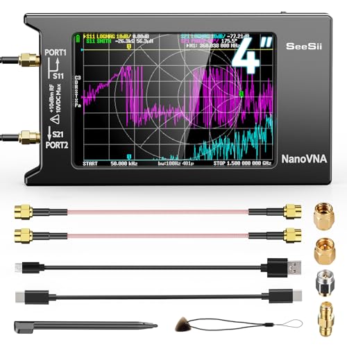
SEESII Upgraded NanoVNA-H4 Vector Network Analyzer, Latest V4.4 9KHz-1.5GHz HF VHF UHF 4" Touch Screen VNA Antenna Analyzer Measures S Parameters,Voltage Standing Wave Ratio, Phase,Delay, Smith Chart
Handheld VNA with touchscreen + SOL kit — S11/S21 lab companion for RF Bench and Antenna Sandbox.
 Sensor
RTL-SDR Blog V4 R828D RTL2832U 1PPM TCXO HF Bias Tee SMA Software Defined Radio with Dipole Antenna Kit
100kHz-1.75GHz low-cost SDR for passively listening to patch array sweeps — compare simulator's beam steering phase Δφ = kd sinθ with over-the-air measured phase progression across 2.4GHz.
 $259.95Sensor
SparkFun GPS-RTK-SMA Breakout - ZED-F9P (Qwiic)
SparkFun Original ZED-F9P RTK GNSS — centimeter-class pose for SLAM / odometry outdoor labs. 10% Originals commission.
 $13.90Kit
AURSINC SMA Calibration Kit and SMA Male to Male Jumper for NanoVNA H H4 F V2 V3 SAA Mini1300 PS100 Vector Network Analyzer Antenna Analyzer
SOL cal standards + SMA jumper for NanoVNA H/H4 — SI Lab and RF Bench SOLT demos.
 $206.99Diagnostic
AURSINC TinySA Ultra+ ZS406 Spectrum Analyzer with 50W N-Type RF Attenuator
Portable spectrum analyzer + attenuator kit — EMI and spur checks next to the RF Bench.
Prices shown were retrieved from the Amazon Product Advertising API on 8 October 2026 and are indicative only — the price and availability on Amazon at the time of purchase apply.
More gear across every app: the full Gear list →
Hardware Kit Builder
Build the physical hardware platform. Select your components below to generate a live, real-time bill of materials and build instructions.
Build this lab
Antenna & RF sounder starter
NanoVNA-H4 + SOL cal + RTL-SDR + TinySA — measure AF, S11, and over-the-air beam steering phase Δφ = kd sinθ₀.
- $85
- $14
- —
- $207
- $135
- $260
Prices shown were retrieved from the Amazon Product Advertising API on 8 October 2026 and are indicative only — the price and availability on Amazon at the time of purchase apply.
Estimated total
—
Prices from Amazon catalog cache · may change
Core solver — TypeScript
// Linear array AF solver — centers array, progressive steering
const c = 299792458;
export function arrayFactor(thetaRad: number, N: number, d: number, k: number, steerRad: number){
  // positions centered
  let re=0, im=0;
  const offset = (N-1)/2;
  for(let n=0; n<N; n++){
    const xn = (n - offset)*d;
    const phi_n = -k*xn*Math.sin(steerRad); // steering
    const psi = k*xn*Math.sin(thetaRad) + phi_n; // = k xn (sinθ - sinθ0)
    re += Math.cos(psi);
    im += Math.sin(psi);
  }
  return Math.hypot(re,im)/N; // normalized 0-1 (uniform weights; the page also offers a Hamming taper, normalizing by Σw)
}
export function elementPattern(thetaRad: number, type: 'iso'|'patch'|'yagi'){
  const ct = Math.cos(thetaRad);
  if(type==='iso') return 1;
  if(type==='patch'){
    return ct<=0 ? 0.08 : Math.pow(ct,1.5);
  }
  // yagi — more directive
  return ct<=0 ? 0.04 : 0.12 + 0.88*Math.pow((1+ct)/2,0.9)*Math.pow(Math.max(0,ct),2.2);
}
export function totalPattern(thetaRad: number, N: number, spacingLambda: number, fGHz: number, steerDeg: number, elem: 'iso'|'patch'|'yagi', ground: boolean){
  const lambda = (c/1e9) / fGHz; // 0.299792458 m per GHz
  const k = 2*Math.PI/lambda;
  const d = spacingLambda * lambda;
  const af = arrayFactor(thetaRad, N, d, k, steerDeg*Math.PI/180);
  let el = elementPattern(thetaRad, elem);
  if(ground && Math.abs(thetaRad) > Math.PI/2) el *= 0.12;
  if(ground && Math.abs(thetaRad) <= Math.PI/2) el *= 1.15;
  return af*el;
}Export · Soft gate
Export array geometry (JSON)
Element count, spacing, steering phase, directivity, beamwidth and sidelobe level, plus patch dimensions to start a PCB layout from. JSON only — no Gerber or DXF file.
File · antenna-array.json
antenna-array.jsonapplication/json+ watermark line on free pathFree download adds a small footer:
/* Export from makerportal.ai — free watermarked build. Unlock …Clean export removes footer. Both are generated fresh from your current sim tuning.
Privacy: email stays in your browser localStorage (mp_export_email_antenna-em-sandbox) + unlock flag (mp_export_unlock_antenna-em-sandbox). If Buttondown username is configured, we also POST to Buttondown (privacy-first mode, no tracking pixels per D-014). See privacy → affiliates & email.
Unlock clean export
Soft gate — no hard paywall, no Clerk. Email stays local unless you explicitly check the newsletter box. Unsubscribe anytime. RSS at /rss.xml.
✓ Lab Pro — clean export on every lab
Your licence unlocks this and every other gated simulator, so there is nothing to enter here. Manage or sign out on the shop page.
✓ Unlocked — clean exports enabled
Stored in mp_export_unlock_antenna-em-sandbox. Clean file omits watermark. Re-lock via browser devtools → localStorage.
Fabricate this design
From sim → PCB
Tuned 2.4 GHz patch array from EM Sandbox — export JSON with dimensions, then order as PCB antenna on PCBWay. Shared Projects pay 10% PCB + 10% SMT when others order your antenna.
What you get
- Stackup CSV / Gerbers tuned in sim (W/H/εr, microstrip Z₀, array spacing → fab notes)
- PCBWay Shared Project if available — 10% PCB + 10% SMT revenue when others order same design
- Privacy-safe — no extra tracking beyond merchant checkout; disclosure in /privacy#affiliates
antenna-em-sandboxNo export yet — tune then exportOrder boards
Order on PCBWayReferral · 5%+↗PCBWay Shared Projects pay 10% PCB + 10% SMT — one fab conversion beats many Amazon electronics clicks.
Frequently asked questions
What is the array factor and why normalize?
For N elements at x_n, AF(θ)= Σ w_n exp(j k x_n sinθ + j φ_n). With uniform weights w_n=1, |AF|_max = N. Normalizing by N yields 0–1 for pattern multiplication by element pattern. Steering uses φ_n = -k x_n sinθ₀, so phase ψ_n = k x_n (sinθ - sinθ₀) places main beam at θ₀. Grating lobes appear when d > λ/(1+|sinθ₀|).
Patch vs Yagi element — how modeled?
Isotropic = 1. Patch (broadside): E_e(θ)=cos^q θ for |θ|≤90° with q≈1.5, else 0.08 for backlobe. Yagi (end-fire-enhanced broadside): narrower, E≈(1+cosθ)/2·cos³θ, mimics reflector/director gain ~6–9dBi. Antenna EM Sandbox array type changes graphics: patch = rectangular metal, Yagi = driven + reflector + directors, but physics is same AF × element.
What does ground plane toggle do?
Ideal infinite PEC at y=0 implements image theory: E_total = E(θ)·2j sin(k h cosθ) for horizontal element height h. We approximate by suppressing back hemisphere |θ|>90° by 12× (21.6 dB) and boosting front by ×1.15, plus drawing PEC line in FDTD view. Full GTD edge diffraction is not included.
How is directivity / HPBW / SLL estimated?
Pattern samples P_i at 720 angles over 360°. D ≈ max(P²)/mean(P²) (2-D cut approximation, reported dBi =10log10 D). True 3-D D would integrate over sphere; we integrate sampled 3-D points for 3-D canvas estimate (small bias). HPBW via linear interpolation where P crosses 0.707 (-3 dB) around peak. SLL scans outside first nulls for largest secondary peak: SLL_dB=20log10(P_sidelobe/P_main).
How does spatial audio know beam alignment?
Virtual listener cursor angle θ_c set by mouse on polar plot. Alignment a = |E(θ_c)|/|E|_max ∈ [0,1]. Web Audio: two detuned saw oscillators (220Hz base + a·320Hz) → Biquad lowpass fc=450+a·6200 Hz → master gain g=0.02+0.42·a². Stereo pan = sin θ_c. At a≈1 filter opens → clear tone, gain loud; off beam → muffled, quiet. Nodes are cleaned on astro:before-swap.
Shareable still
The instrument, captured—not illustrated.
This 16:9 frame is rendered from the real browser instrument above. It is the page's canonical preview for image search, link unfurls, and posts that need to show what the tool actually does.
Download 1280 × 720 JPEG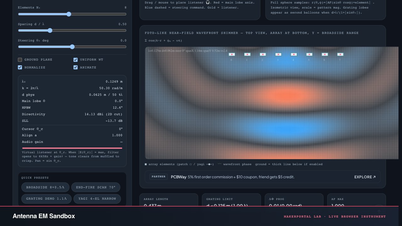
Continue the experiment