Playground · research instrument
SignalGaN FOC Drive — SVPWM Inverter + Motor
GaN/SiC three-phase inverter driving a PMSM with field-oriented control. Tune Vdc, Iq*/Id*, f_sw up to 100 kHz, dead-time ns, torque load, p, Rs/Ls. Watch stator flux spin, 3-phase currents, Clarke/Park live, SVPWM hexagon with sector times, dead-time distortion V_dead=td·fsw·Vdc·sign(I), thermal ΔT=Rth·Psw and hear whine pitch-tracked to fe=p·ωm/2π.
Independent research instrument — not claimed as MakerPortal shipped product code. Methods, equations, assumptions, and limitations are disclosed so you can inspect what the page does and does not establish.
Inverter & Motor Tuning
DC-link & FOC setpoint — Iq torque, Id flux
GaN/SiC Switching — dead-time & f_sw
Motor — PMSM SPMSM
Stator flux rotation — αβ + dq frame (ψs)
SVPWM hexagon — Vref = Vdc/√3 limit, sector T1/T2
3-phase currents — Clarke/Park live (ia,ib,ic & id,iq)
Thermal rise — ΔT=Rth·Psw, Psw≈fsw·Esw, efficiency
Anatomy of the GaN FOC drive
Power stage → FOC chain
- GaN half-bridges: 3× half-bridge, Vdc 12-80 V, 2-level. GaN HEMT Rds(on) 3-80 mΩ, tr 15 ns tf 10 ns vs Si 80 ns. Dead-time td 0-500 ns inserts blanking to avoid shoot-through.
- SVPWM: Given vdq commands from PI, inverse Park → vαβ, SVPWM computes sector 1-6, T1,T2,T0 duty. Linear limit circle Vdc/√3 inside hexagon radius 2·Vdc/3.
- Dead-time distortion: Body diode conduction clamps phase to opposite rail, average error V_dead = td·fsw·Vdc·sign(I). Modeled as additive ΔVαβ via Clarke of per-phase V_dead·sign(i).
- PMSM motor: SPMSM Ld≈Lq=Ls. Electrical vd = R·id + L·did/dt - ωe·L·iq, vq = R·iq + L·diq/dt + ωe·L·id + ωe·ψm. Torque Te=1.5·p·ψm·iq (id=0).
- Mechanical: J·dωm/dt = Te - Tload - B·ωm, ωe = p·ωm, θe = ∫ωe dt. Inertia J tunes how fast speed ramps.
- Loss / thermal: Pcond=3·Irms²·Rds, Psw≈ Σ Vdc·|i|·(tr+tf)/2·fsw, Rth models heatsink, first-order LPF τ=2 s → ΔT=Rth·P, Tj=Tamb+ΔT.
Dead-time & thermal
Reducing td from 2 µs Si to 80 ns GaN cuts distortion voltage ~25×, enabling silent 40-100 kHz operation.
Controls & sensing visualization
- Flux canvas: stator flux ψs = L·Is + ψm rotor, dq frame rotating at θe. When id=0, ψs leads ψm by 90° (iq axis).
- Currents canvas: 1000-sample rolling buffer ~2 electrical periods. Shows ia,ib,ic sinusoids, plus id,iq decoded live. Dead-time shows as zero-crossing flattening.
- SVPWM canvas: hexagon V1(100)..V6(101) active, zeros V0,V7 center. Vref yellow dot, T1/T2 arrows along two bounding vectors, red halo width ∝ V_dead/Vref.
- Thermal canvas: stacked area Pcond vs Psw, line Tj progression, efficiency η=Pmech/(Pmech+Ploss). Over-temp >125 °C flags fault.
- Audio: 2 oscillators: carrier fe_hz = p·ωm/2π. Audible f = 5k + fe·55 + 1.2k·|Te| + fsw_mod (fsw>20k gives ultrasonic sideband folded). Gain ∝ torque+speed.
- FOC PI: Kp≈L·bw, Ki≈R·bw, bw≈ 2π·400 Hz default. Decoupling feedforward ωe·L·I removes cross-axis.
PMSM dq model (SPMSM)
Discretized semi-implicit Euler at 4 kHz control, 0.25 ms.
Equations of motion
Clarke / Park transforms
Amplitude invariant preserves peak sinusoid as dq DC.
FOC id=0 & SVPWM
MTPA id=0 for SPMSM, field weakening id negative above base speed.
Switching, power, audio
fe is electrical, fsw is ultrasonic carrier GaN pushes >30 kHz.
Gear behind this build
GaN stack · 7 picks
Hardware picks7
 $444.75Diagnostic
Fluke 87V Industrial Digital Multimeter, for Advanced Troubleshooting, Measures 1000 V AC/DC, Peak Min/Max, Low Pass Filter, Includes TL75 Test Leads, AC175 Alligator Clips, 80BK Temp Probe
True-RMS meter for phase current measurement and inductor DCR loss — validate simulator's I_q setpoint vs measured phase current sine with THD from SVPWM harmonics.
 $12.69Diagnostic
HiLetgo USB Logic Analyzer Device with EMI Ferrite Ring USB Cable 24MHz 8CH 24MHz 8 Channel UART IIC SPI Debug
Budget 8-ch USB logic analyzer (sigrok/PulseView). Useful for RTOS GPIO timing and SI digital demos — not a Saleae substitute in bandwidth.
 Kit
KitFNIRSI 2C23T 3 in 1 Handheld Oscilloscope Multimeter DDS Generator, 2 Channels, 10MHz Bandwidth, 50MSa/s Sampling Rate, 10000 Counts, Voltage, Current, Capacitor, Resistor, Diode Test
Feed a square wave into your scope and see its Fourier epicycles live — same harmonic decomposition (odd k only) this page animates as rotating vectors.
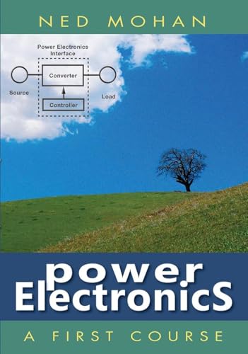 $53.63Book
Power Electronics: A First Course
Derives SVPWM V_ref = V_dc/√3, dq transformation, and FOC i_d=0 control — complete theory behind simulator's Park/Clarke, PI current loops, and flux observer.
 $17.50Tool
SparkFun OpenLog
SparkFun Original OpenLog — serial data logger for FOC / RTOS capture sessions. 10% Originals commission.
 $29.50Microcontroller
SparkFun RedBoard Plus
SparkFun Original Uno-compatible RedBoard Plus — Qwiic-ready teaching MCU for FreeRTOS demos and sensor labs. 10% Originals commission.
 $23.80Microcontroller
Teensy 4.0
600 MHz Cortex-M7 — high-rate control loops and DSP on the RTOS / FOC benches. Carried by SparkFun (third-party PJRC; tracked referral).
Prices shown were retrieved from the Amazon Product Advertising API on 8 October 2026 and are indicative only — the price and availability on Amazon at the time of purchase apply.
More gear across every app: the full Gear list →
Hardware Kit Builder
Build the physical hardware platform. Select your components below to generate a live, real-time bill of materials and build instructions.
Build this lab
GaN FOC bench starter
Teensy 4.0 + RedBoard Plus + OpenLog + logic analyzer — close the loop from SVPWM simulation to phase-current capture. RedBoard & OpenLog are SparkFun Originals (10%).
- $30
- $24
- $18
- $13
- $445
- —
- $54
Prices shown were retrieved from the Amazon Product Advertising API on 8 October 2026 and are indicative only — the price and availability on Amazon at the time of purchase apply.
Estimated total
$83
Prices from Amazon catalog cache · may change
Core solver — TypeScript
// FOC core — Clarke, Park, SVPWM, PMSM dq model
type DQ = { d:number; q:number };
type AB = { a:number; b:number };

const SQRT3 = Math.sqrt(3);

// Clarke amplitude-invariant (ia+ib+ic=0)
function clarke(ia:number, ib:number, ic:number): AB {
  return { a: (2/3)*(ia - 0.5*ib - 0.5*ic), b: (2/3)*(SQRT3/2*ib - SQRT3/2*ic) };
}
function invClarke(ab:AB): [number,number,number] {
  const ia = ab.a;
  const ib = -0.5*ab.a + SQRT3/2*ab.b;
  const ic = -0.5*ab.a - SQRT3/2*ab.b;
  return [ia, ib, ic];
}
function park(ab:AB, theta:number): DQ {
  const c=Math.cos(theta), s=Math.sin(theta);
  return { d: ab.a*c + ab.b*s, q: -ab.a*s + ab.b*c };
}
function invPark(dq:DQ, theta:number): AB {
  const c=Math.cos(theta), s=Math.sin(theta);
  return { a: dq.d*c - dq.q*s, b: dq.d*s + dq.q*c };
}

function svpwm(valpha:number, vbeta:number, Vdc:number, fsw:number){
  const Vref = Math.hypot(valpha, vbeta);
  const Vlim = Vdc / Math.sqrt(3); // linear limit
  const V = Math.min(Vref, Vlim);
  let ang = Math.atan2(vbeta, valpha); // 0..2pi
  if(ang<0) ang+=2*Math.PI;
  const sector = Math.floor(ang / (Math.PI/3)) + 1; // 1..6
  const theta = ang - (sector-1)*(Math.PI/3); // 0..60deg
  const T = 1/fsw;
  const T1 = Math.sqrt(3)*T*V/Vdc*Math.sin(Math.PI/3 - theta);
  const T2 = Math.sqrt(3)*T*V/Vdc*Math.sin(theta);
  const T0 = Math.max(0, T - T1 - T2);
  const mod = V / Vlim;
  return { Vref, Vlim: V, mod, ang, sector, theta, T1, T2, T0, T };
}

// dead-time voltage error per phase
function vDead(td:number, fsw:number, Vdc:number, i:number): number {
  // V_dead = td * fsw * Vdc * sign(I)  (average over Ts)
  return td * fsw * Vdc * Math.sign(i);
}

// PMSM dq electrical dynamics
function dqDeriv(id:number,iq:number,vd:number,vq:number,we:number,R:number,L:number,psi:number){
  const didt = (vd - R*id + we*L*iq)/L;
  const diqt = (vq - R*iq - we*L*id - we*psi)/L;
  return { didt, diqt };
}
function torque(p:number, psi:number, iq:number, Ld:number, Lq:number, id:number){
  return 1.5 * p * (psi*iq + (Ld - Lq)*id*iq);
}

// PI + feedforward
function piFOC(e:number, int:number, Kp:number, Ki:number, we:number, L:number, iq:number, extra=0){
  return Kp*e + Ki*int + we*L*iq + extra;
}
Frequently asked questions
What does FOC with id = 0 mean?
For a surface PM motor Ld≈Lq, torque Te=1.5·p·ψm·iq + 1.5·p·(Ld-Lq)·id·iq reduces to 1.5·p·ψm·iq when id=0. Setting id_sp=0 puts all stator current into torque-producing q-axis, keeps the stator flux |ψs| = sqrt((Ld·id+ψm)²+(Lq·iq)²) minimal and maximizes efficiency below base speed. Field weakening uses id<0 to oppose ψm and extend speed.
How do Clarke and Park transforms work?
Clarke: 3-phase ia,ib,ic (ia+ib+ic=0) → αβ0: iα=2/3·(ia-0.5·ib-0.5·ic), iβ=2/3·(√3/2·ib-√3/2·ic), power/amplitude variant. Park rotates αβ by electrical angle θe: id=iα·cosθe+iβ·sinθe, iq=-iα·sinθe+iβ·cosθe. This locks the reference to the rotor so AC sinusoids become DC setpoints the PI can regulate. Inverse Park does vdq → vαβ for SVPWM.
What is SVPWM limit Vref = Vdc/√3 and the hexagon?
A two-level inverter can only output 6 active vectors V1..V6 at 60° steps plus two zeros. Their tips form a hexagon radius 2·Vdc/3 (amplitude invariant). The largest inscribed circle for linear modulation is Vdc/√3. Modulation index M=Vref/(Vdc/√3). T1=√3·Tsw·Vref/Vdc·sin(60°-θ), T2=√3·Tsw·Vref/Vdc·sinθ, T0=Tsw-T1-T2. Over M>1 we saturate to hexagon edge — six-step.
Why does dead-time cause voltage distortion?
To avoid shoot-through both FETs are off for td. Current freewheels through body diode, clamping phase voltage to ±Vdc/2 opposite sign of current. Average error per switching period averages to V_dead = td·fsw·Vdc·sign(I). It appears as 5th/7th harmonics, zero-crossing distortion, and torque ripple. GaN needs 10-80 ns vs Si IGBT 1-3 µs, so V_dead drops 10-30× at same fsw, enabling 50-100 kHz silent drives.
How is temperature rise and audio modeled?
Conduction Pcond = 3·Irms²·Rds(on). Switching Esw≈Vdc·|I|·(tr+tf)/2 per edge, Psw≈ fsw·Vdc·Iavg·(tr+tf). Total P = Pcond+Psw, ΔT=Rth·P filtered τ_th≈2s. Junction Tj=Tamb+ΔT. Audio: electrical freq fe=p·ωm/2π. Motor whine = carrier at fcarrier=clamp(5000+fe·55 + 1200·|Te|, 5000, 19000) Hz, amp modulated by |iq| and switching sidebands at fsw ± k·fe. GaN high fsw pushes carrier above 15 kHz where human sensitivity rolls off.
Shareable still
The instrument, captured—not illustrated.
This 16:9 frame is rendered from the real browser instrument above. It is the page's canonical preview for image search, link unfurls, and posts that need to show what the tool actually does.
Download 1280 × 720 JPEG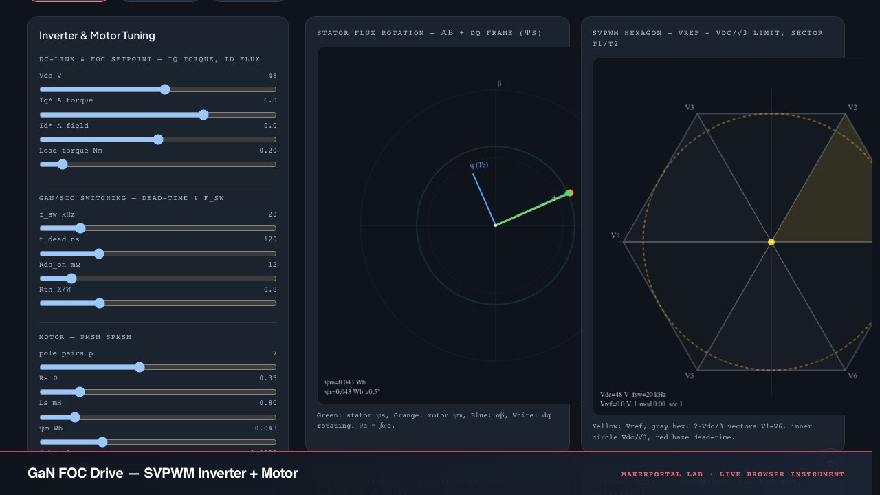
Continue the experiment